5 ‒ Installation and Electrical Connection | P1PY201 ‒ Laser Distance Sensor ToF 17
• If using IO-Link, connect the sensor to 18…30 V DC.
• If not using IO-Link, connect the sensor to 10…30 V DC.
• The blue supply voltage indicator lights up.
• Adjust the sensor so that the light spot strikes the object to be detected/measured.
DANGER
Risk of personal injury or property damage due to electric current.
Voltage-conducting parts may cause personal injury or damage to equipment.
à The electric device may be connected by appropriately qualified personnel only.
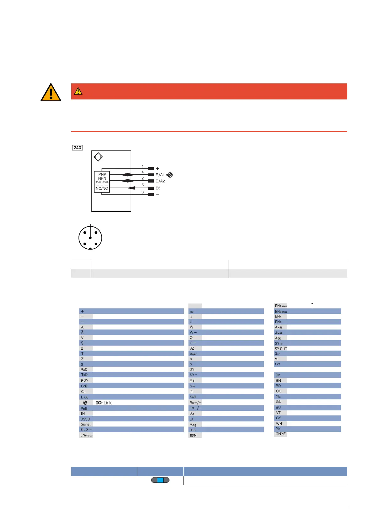
1 Brown 2 White
3 Blue 4 Black
5 Gray
Legend
Wire Colors according to IEC 60757
Platinum measuring resistor
not connected
Test Input
Test Input inverted
Trigger Input
Ground for the Trigger Input
Analog Output
Ground for the Analog Output
Block Discharge
Valve Output
Valve Control Output +
Valve Control Output 0 V
Synchronization
Ground for the Synchronization
Receiver-Line
Emitter-Line
Grounding
Switching Distance Reduction
Ethernet Receive Path
Ethernet Send Path
Interfaces-Bus A(+)/B(–)
Emitted Light disengageable
Magnet activation
Input confirmation
Contactor Monitoring
Black
Brown
Red
Orange
Yellow
Green
Blue
Violet
Grey
White
Pink
Green/Yellow
Supply Voltage +
Supply Voltage 0 V
Supply Voltage (AC Voltage)
Switching Output (NO)
Switching Output (NC)
Contamination/Error Output (NO)
Contamination/Error Output (NC)
Input (analog or digital)
Teach Input
Time Delay (activation)
Shielding
Interface Receive Path
Interface Send Path
Ready
Ground
Clock
Output/Input programmable
Power over Ethernet
Safety Input
Safety Output
Signal Output
Ethernet Gigabit bidirect. data line (A-D)
Encoder 0-pulse 0-0 (TTL)
Encoder A/A (TTL)
Encoder B/B (TTL)
Encoder A
Encoder B
Digital output MIN
Digital output MAX
Digital output OK
Synchronization In
Synchronization OUT
Brightness output
Maintenance
reserved
PT
5.3 Diagnosis
Indicator Status Meaning
Power LED Sensor ready for operation
 Loading...