31
I N S TA L L E R S e c t i o n ( e n )
7113156.01 (1-05/13)
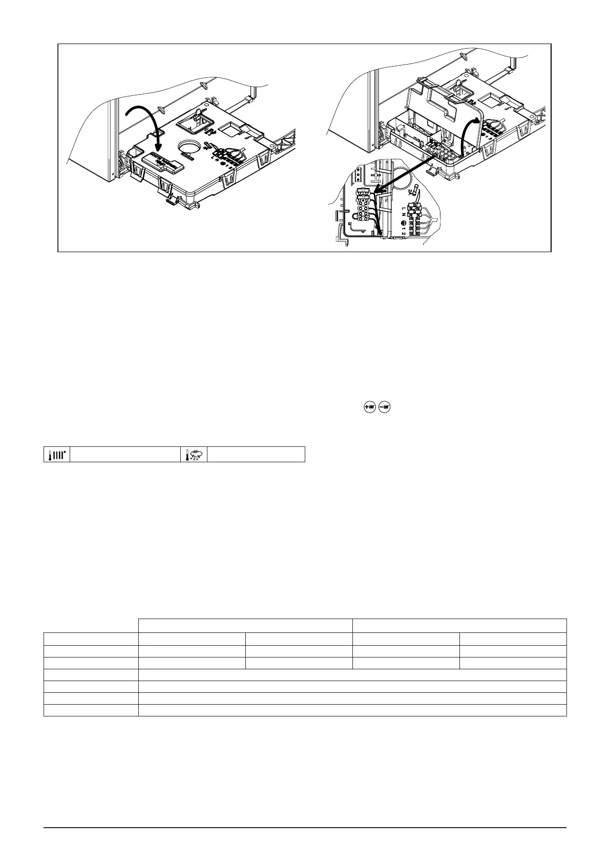
11.1 CONNECTING THE ROOM THERMOSTAT
To connect the Room Thermostat to the boiler, proceed as follows:
• access the power terminal block as described in the ELECTRICAL CONNECTIONS section;
• remove the jumper on terminals (1) and (2);
• thread the two-wire cable through the grommet and connect it to these two terminals.
11.2 CONNECTING THE EXTERNAL PROBE
To connect the External Probe, supplied as an accessory, to the boiler, proceed as follows:
• access the power terminal block as described in the ELECTRICAL CONNECTIONS section;
• connect the external probe to the two RED wires tted with faston covers;
• with the external probe connected, select the “kt” climate curve by pressing , selecting from the available ones (0...90),
see the curves chart in “SECTION” E at the end of this manual (the preset curve is 0).
KEY TO CURVE CHART Kt - “SECTION” E
Flow temp Outside temp
12. GAS VALVE
12.1 GASCONVERSION
The Technical Assistance Service can convert this boiler to natural gas (G20) or LPG (G31). Carry out the following operations:
A) replace the main burner injectors;
B) parameterise the electronic board;
C) mechanically calibrate the gas valve pressure regulator;
D) electronically calibrate the gas valve;
E) nal checks.
24 F 18 F
Parameter G20 G31 G20 G31
F02 0 1 0 1
F08 55 60 100 100
F18 18
F45 1
F48 100
F64 1