35
I N S TA L L E R S e c t i o n ( e n )
7113156.01 (1-05/13)
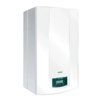
Parameter
Description of
parameters
Factory settings
Parameter Description of
parameters
Factory settings
24 F - 18 F 24 F - 18 F
F19 Factory setting 001 F44 Factory setting 000
F20 Factory setting 000
F45 Factory setting
(this value depends on
valve calibration)
F21 Factory setting 030
F22 Factory setting 110 F46 Factory setting 015
F23 Factory setting 010 F47 Factory setting 007
F24 Factory setting 005
F48 Factory setting
(this value depends on
valve calibration)
F25 Factory setting 000
F26 Factory setting 165 F49 Factory setting 105
F27 Factory setting 010 F50 Factory setting 100
F28 Factory setting 070 F51 Factory setting 005
F29 Factory setting 020 F52 Factory setting 020
F30 Factory setting 000 F53 Factory setting 100
F31 Factory setting 180 F54 Factory setting 000
F32 Factory setting 170 F55 Factory setting 003
F33 - F34 Factory setting 004 F56 Factory setting 025
F35 Factory setting 015 F57 Factory setting 000
F36 Factory setting 020 F58 Factory setting 025
F37 Factory setting 003 F59 Factory setting 005
F38 Factory setting 000 F60 Factory setting 120
F39 Factory setting 067 F61 Factory setting 015
F40 Factory setting 120 F62 Factory setting 030
F41 Factory setting 010 F63 Factory setting 025
F42 Factory setting 042 F64 Factory setting 000
F43 Factory setting 001
15. TROUBLESHOOTING SERVICE FAULTS
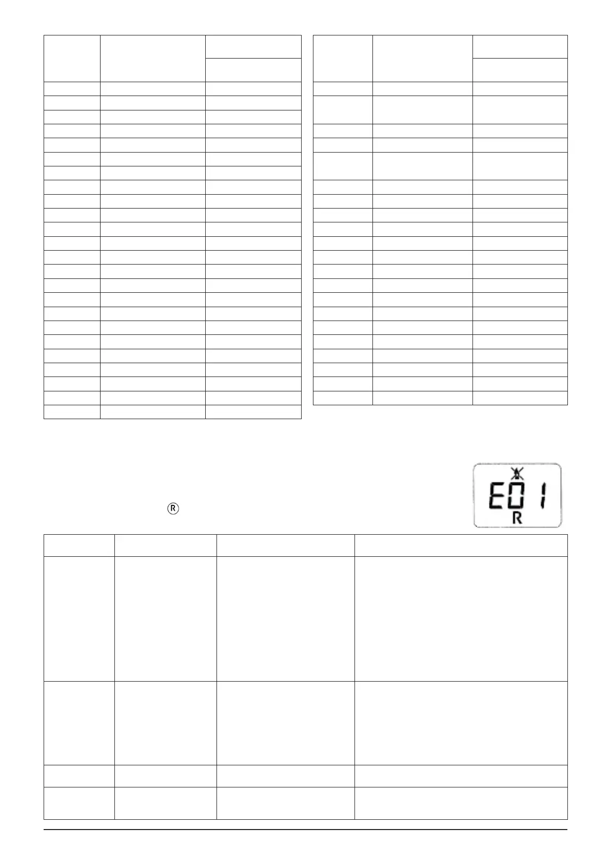
The faults shown on the display are identied with the symbol “E” and a number (fault code). For a
complete list of faults, see the following table.
If “R” appears on the display the fault must be RESET by the user.
To reset, press and hold down for at least 2 seconds. If this fault persists, call the Authorised Service
Centre.
CODE
DISPLAYED
FAULT POSSIBLE REASON SERVICE ACTION
E01 Shut down for ignition
failure.
• No inlet gas pressure.
• Ignition switch-ame sensor wire
interrupted.
• Flame sensing electrode faulty or
incorrectly positioned.
• Gas valve faulty.
• Electronic board faulty.
• Check that the gas valve is open and there is no air in
the gas supply circuit.
• Check the gas supply pressure.
• Check the wire is uninterrupted and makes good
contact with the ame sensing electrode and the
ignition switch.
• Check the connections between the gas valve and the
electronic board.
• Check the ame sensing electrode is in good
condition and in the right position (see the
POSITIONING THE IGNITION AND FLAME-
SENSING ELECTRODE section).
E02 Shut down by safety
thermostat.
• No water in the primary circuit
(pump blocked or exchanger
obstructed).
• Limit thermostat faulty.
• Limit thermostat wiring
interrupted.
• CH ow NTC probe faulty.
• Electronic board faulty.
• Check pump operation (unscrew the front cap and
release the pump impeller with a screwdriver).
• Check the pump power input wiring.
• Check that the limit thermostat is undamaged and
replace it if necessary.
• Check the continuity of the limit thermostat wiring.
• Check the CH ow NTC probe (*).
• Check whether the exchanger is clogged.
E03 Board conguration error. • Parameter F43 has not been set
correctly.
• Set parameter F43 with the value indicated in the
table in the SETTING PARAMETERS section.
E04 Safety error due to
ignition failure or frequent
ame loss.
• See the reasons indicated in E01.
• See the reasons indicated in E42.
• See the actions indicated in E01.
• See the actions indicated in E42.
 Loading...