Lit. No. 27366, Rev. 01 February 15, 2008
17
SYSTEM OVERVIEW – HYDRAULIC
NOTE: Overtightening JIC hose
fitting ends will result in a
fractured fitting.
Do not use thread sealant or tape on
hoses and fittings. This could
damage product.
Use the following procedure and
fitting orientation illustrations to
install SAE O-ring fittings in valve
block and rams.
1. Remove plug from ram or
manifold port. Use a rag to catch
residual fluid when removing
manifold plugs.
2. Turn jam nut on fitting as far back
as possible.
3. Lubricate O-ring with clean
hydraulic fluid.
4. Screw fitting into port by hand as
far as it will go. The washer
should contact port face and
shoulder of jam nut threads.
5. Unscrew fitting to proper position,
no more than one full turn.
6. Use one wrench to hold fitting
body in position and tighten the
jam nut with another wrench until
the washer again contacts port
face. Tighten 1/8–1/4 turn to lock
fitting in place.
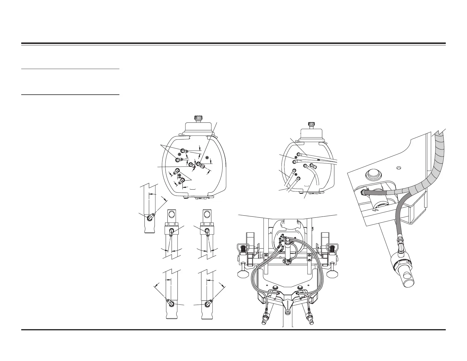
HYDRAULIC FITTING AND HOSE INSTALLATION
PS Rod End
PS Base End
DS Rod End
Lift Ram
45°
90°
Elbow
10°10°
90°
Elbow
45°
DS Base End
45°
90°
Elbow
Angle Rams
Hydraulic Unit
Long 90°
Elbows
90° Elbow
and Cap
Long 90°
Elbows
90°
Elbow
10°
45°
45°
30°
30°
10°
Use the following procedure and
illustrations to install hydraulic
hoses.
1. Attach all hoses to fittings,
routing hoses as shown. Leave
hoses finger tight at this time.
1/4" x 36" Hose
To Passenger-
Side Rod (Front)
3/8" x 45" Hose
To Driver-Side
Base (Rear)
3/8" x 38" Hose
To Passenger-
Side Base (Rear)
1/4" x 12" Hose
To Lift Ram
1/4" x 42" Hose
To Driver-Side
Rod (Front)
2. Wrap angle ram hoses with
protective hose wrap as shown.
Start wrap on base end hose so
wrap covers diagonal brace.
Group hoses away from brace
and continue wrapping, forming a
smooth outward loop to the
hydraulic unit.
3. Using a wrench to hold the hose
end in position, tighten all hose
fittings 1/8–1/4 turn past finger
tight.
Excerpts taken from MVP PLUS™ Snowplow Installation Instructions (Lit. No. 44229, Rev. 05).
 Loading...