Lit. No. 27366, Rev. 01 February 15, 2008
10
SYSTEM OVERVIEW – BLADE, T-FRAME & LIFT ASSEMBLIES
Config. 1
Config. 2
Config. 3
Config. 4
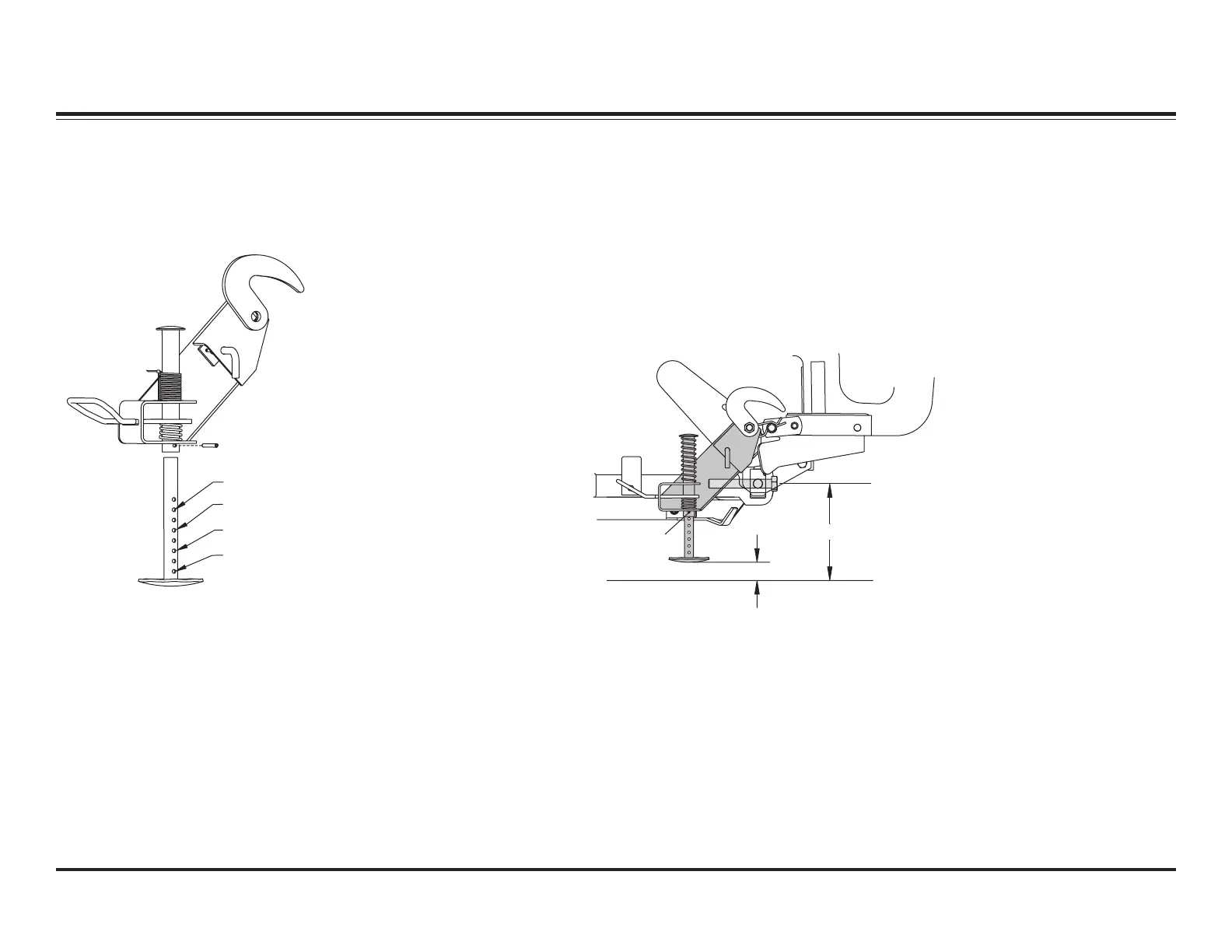
INITIAL STAND SHOE SETUP
The illustration below shows the
recommended starting positions for
configuring your stand shoes.
9-3/4" to 11-1/4"
1-3/8" to 2-1/8"
Roll Pin
STAND SHOE ADJUSTMENT
1. Attach snowplow to the vehicle
mount. With snowplow lowered
to the ground and on level
pavement, measure the
dimension from the ground to the
center of the pivot bar cap screw.
This dimension must be 9-3/4" to
11-1/4".
2. With the snowplow attached and
on the ground, place the stand
arm in the lower position with the
lock pin engaged and with the
stand shoe fully retracted in the
"up" position. Measure the
distance from the ground to the
bottom of the stand shoe. This
distance should be 1-3/8" to
2-1/8". The stand can be
adjusted to achieve this
dimension by removing the roll
pin and selecting the proper hole
in the stand stem. When the
stand height is correct, cut and
remove the spring tie.
Excerpts taken from MVP PLUS™ Snowplow Installation Instructions (Lit. No. 44229, Rev. 05).
 Loading...