Lit. No. 27366, Rev. 01 February 15, 2008
75
TROUBLESHOOTING GUIDE
SOLENOID COIL ACTIVATION TEST (SCAT)
Off-Truck Testing
1. Remove the hydraulic unit covers.
2. Remove the short red cable from
the motor relay.
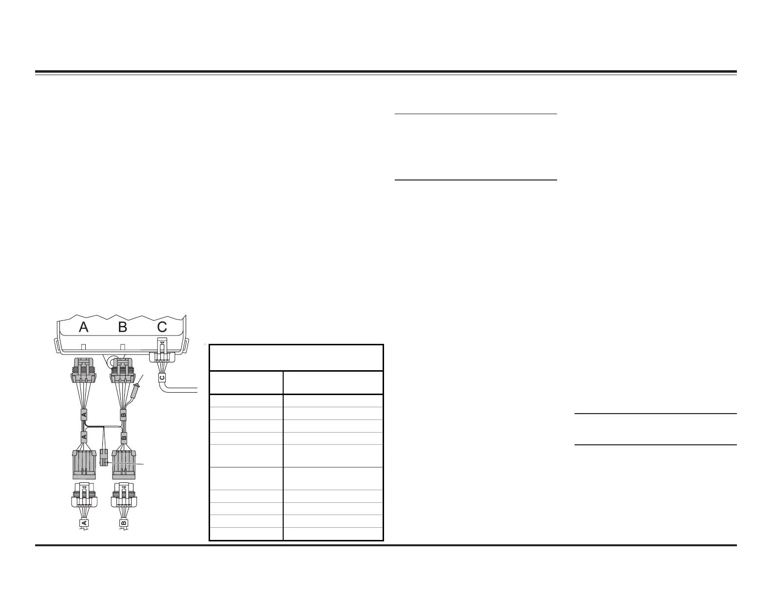
3. Unplug the snowplow connectors
from Ports A and B of the Plow
Module.
4. Connect the diagnostic harness
connectors A and B to the
matching ports on the Plow
Module (A to A and B to B).
5. Plug the connectors removed from
the Plow Module into the matching
connectors on the diagnostic
harness (A to A and B to B).
6. Connect the snowplow control into
the 4-position control connector on
the diagnostic harness.
7. Connect a 12V power source to
the snowplow battery cable
(POSITIVE [+] 12V to the red wire
and NEGATIVE [–] to the black
wire). Turn ON the power source.
8. Turn the snowplow control ON
and perform a Solenoid Coil
Activation Test (SCAT). See the
chart below for solenoid numbers
and functions.
29290-1
Diagnostic
Harness
4-Position
Control
Connector
LED
Plow Module (on hydraulic unit)
NOTE: The green LED on the
diagnostic harness will illuminate
when the motor relay function is
activated. This light only tests the
Plow Module's motor relay output.
9. After completing the SCAT test,
turn the snowplow control OFF
and disconnect the power source.
10. Perform any required repairs and
retest as needed. Always
disconnect the snowplow and
vehicle battery cables before
removing the diagnostic harness.
11. Reconnect the short red cable
assembly to the motor relay.
INDIVIDUAL SOLENOID COIL
TEST
1. Remove both wires from coil
terminals.
2. Attach an ohmmeter across the
coil terminals.
3. A reading that is not
approximately 7 ohms indicates
coil is damaged and must be
replaced.
4. Attach an ohmmeter to one coil
terminal and to the steel washer
at the end of the coil.
5. A reading that is not "open"
indicates that the coil has internal
shorts and needs to be replaced.
6. If both readings are OK
(i.e., approximately 7 ohms
across terminals and "open"
between terminal and washer),
then the coil is good.
NOTE: A good coil will draw
approximately 1.5 Amp.
Solenoid Coil Activation
Test (SCAT) Chart
Control
Function
Component(s)
Activated
Raise S2, Motor Relay
Lower S3
Angle Right S5, S8, S10, Motor Relay
Angle Left S4, S6, S9, Motor Relay
Scoop S4, S7, S8, S11, Motor
Relay
Retract (Vee) S1, S4, S6, S8, S10,
Motor Relay
Wing (Right – Out) S8, S11, Motor Relay
Wing (Right – In) S1, S8, S10, Motor Relay
Wing (Left – Out) S4, S7, Motor Relay
Wing (Left – In) S1, S4, S6, Motor Relay
Excerpts taken from Diagnostic Harness Kit Installation Instructions (Lit. No. 29289, Rev. 03).

 Loading...