Lit. No. 27366, Rev. 01 February 15, 2008
9
Configuration 3
Configuration 4
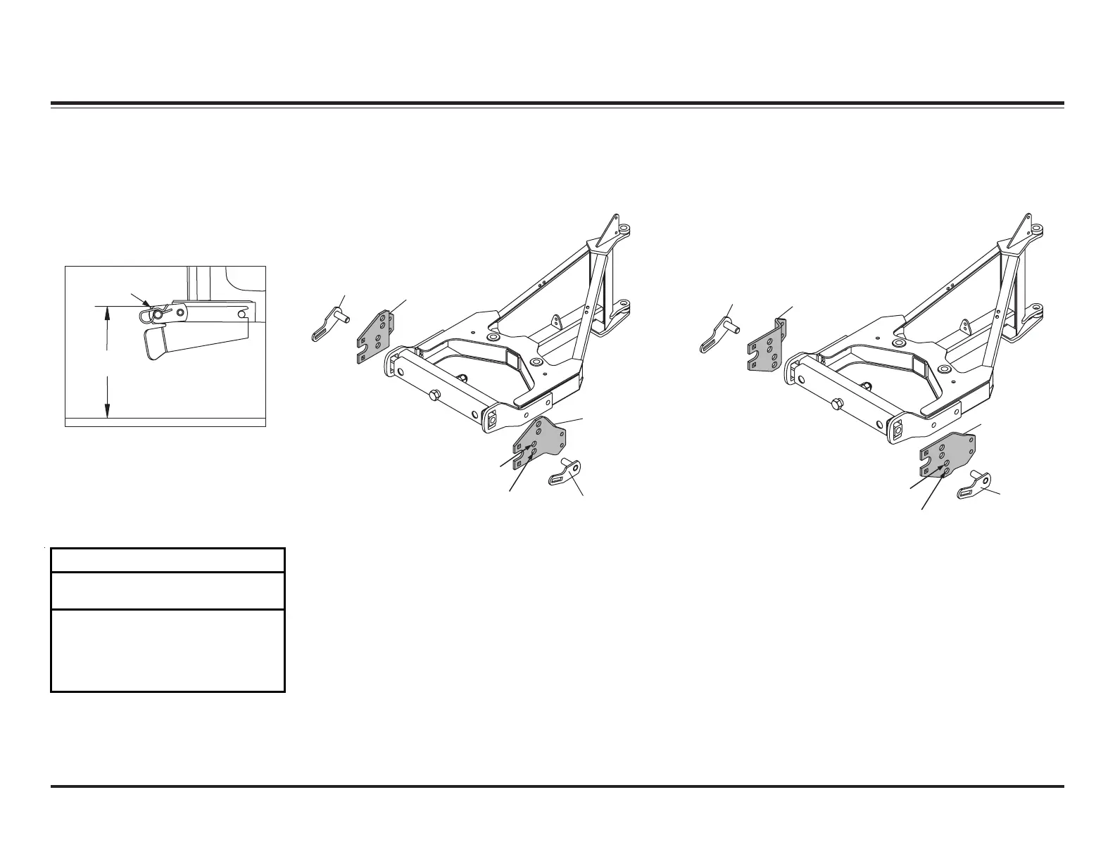
Pivot Pin
Pivot Pin
Pivot Plate A
(Flat Side Up)
Pivot Plate B
(Flat Side Up)
PIVOT PLATES
1. Measure the distance "d" from
the ground to the top edge of the
receiver bracket. Measure both
sides and determine average
value "d".
2. Use dimension "d" from Step 1,
and the following chart to
determine the proper pivot plate
mounting position and pivot hole
selection.
d
Top Edge of
Receiver
Pivot Plate A
(Bevel Side Up)
Pivot Pin
Pivot Pin
Pivot Plate B
(Bevel Side Up)
Configuration 1
Configuration 2
Pivot Plate Mounting and Hole Positions
for Configurations 1 & 2
Pivot Plate Mounting and Hole Positions
for Configurations 3 & 4
SYSTEM OVERVIEW – BLADE, T-FRAME & LIFT ASSEMBLIES
Pivot Plate Configuration Chart
Dimension
"d" Configuration
Stacking
Stop
13.0" – 14.5" 1 No
14.5" – 16.0" 2 No
16.0" – 17.5" 3 No
17.5" – 19.0" 4 Yes
Excerpts taken from MVP PLUS™ Snowplow Installation Instructions (Lit. No. 44229, Rev. 05).
 Loading...