Lit. No. 27366, Rev. 01 February 15, 2008
8
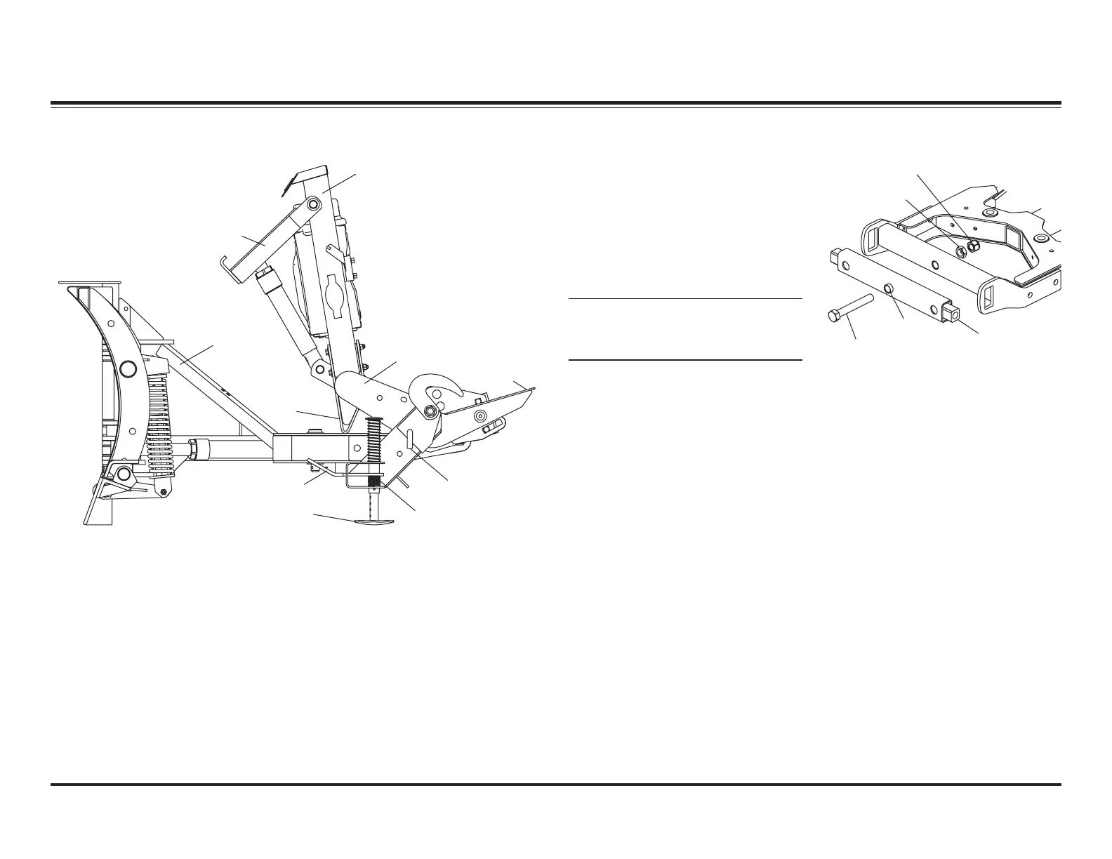
SYSTEM OVERVIEW – BLADE, T-FRAME & LIFT ASSEMBLIES
SNOWPLOW COMPONENTS
Stacking
Stop
Shoe
Handle
T-Frame
Assembly
Upper Lift Frame
Lower Lift
Frame
Lock Pin
Stand
Plow
Horn
Lift Arm
1. Install a 1" jam nut and tighten to
25 ft-lb, then loosen 1/16 turn.
2. Hold 1" cap screw and jam nut to
prevent rotation, and install
1" locknut. Tighten locknut
securely against jam nut.
NOTE: When properly adjusted,
pivot bar should pivot freely
without any looseness.
1" Locknut
1" Jam Nut
Pivot Bar
Pivot
Bushing
1" x 7"
Cap Screw
SECURING PIVOT BAR TO T-FRAME
Excerpts taken from MVP PLUS™ Snowplow Installation Instructions (Lit. No. 44229, Rev. 05).
 Loading...