Lit. No. 27366, Rev. 01 February 15, 2008
38
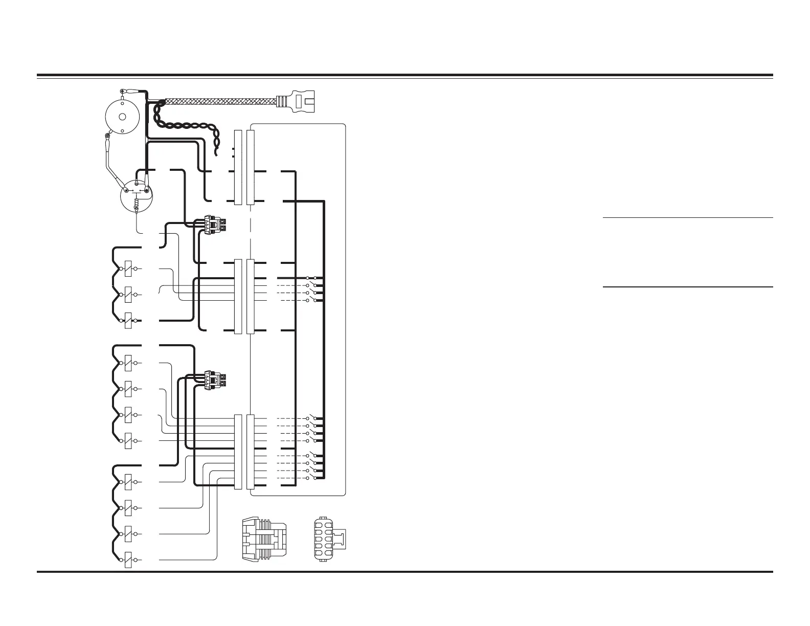
LOWER – ELECTRICAL
System Response
1. By activating the LOWER
function on the cab control, the
control sends a signal to the
Plow Module to complete the
ground path for the electrical
circuit, activating solenoid
cartridge valve S3.
2. With the weight of the snowplow
on the rod end of the lift ram and
S3 cartridge valve shifted, the lift
ram retracts. Hydraulic fluid is
pushed out of the base end,
through S3 and back to the
reservoir.
NOTE: Battery voltage is supplied
to the Plow Module, the motor
relay and the 11 solenoid coils
when the snowplow is connected
to the vehicle.
RED
Plow Module
4 Amp Fuse: Motor
Relay
4 Amp Fuse: S1, S2, S3
Pump
Motor
Motor
Relay
GG
A
A
A
B
C
E
D
F
B
C
D
E
F
H
KK
H
JJ
A
B
A
GG
B
D
C
F
E
D
B
C
F
E
H
KK
H
JJ
4 Amp Fuse: S8, S9,
S10, S11
4 Amp Fuse: S4, S5,
S6, S7
Wire Side View
10-Pin Connector
BB
A
C
A
HH
D
C
F
G
EE
D
C
F
G
K
J
K
J
WHT
TAN
BLK
RED
RED
RED
S1
S2
S3
BLK
RED
RED
WHT
GRN
BLU
RED
12V
COM
12V
M/R
S2
S3
S1
12V
S10
S9
S8
S11
S7
S6
GRY
RED
WHT
GRN
ORN
RED
BRN
YEL
S4
S5
BLK
TAN
S9
S8
S5
12V
S10
S11
S7
S6
S4
12V
E
D
B
C
A
F
G
J
H
K
+
–
BLK
 Loading...