Lit. No. 27366, Rev. 01 February 15, 2008
82
TROUBLESHOOTING GUIDE
Inspection
1. Remove the valve stem, ball,
spacer and spring.
2. Look for broken or damaged
parts, contamination or missing
or damaged O-rings.
3. If parts are OK, place ball on
hard wood block, hold stem seat
on ball and lightly strike top of
stem with a hammer. This will
seat the ball and valve stem.
4. Apply a light coat of anti-seize or
grease to stem threads.
Lubricate O-rings with hydraulic
fluid. Reassemble components
into valve block.
CAUTION
Be careful to strike stem
squarely. You can bend stem if
you do not strike it squarely.
CAUTION
Never operate the unit while
adjusting the relief valve.
Doing so will damage the relief
valve O-rings.
Adjustment
1. Screw stem in until spring is fully
compressed.
2. Back out (counterclockwise) the
number of turns in the following
chart.
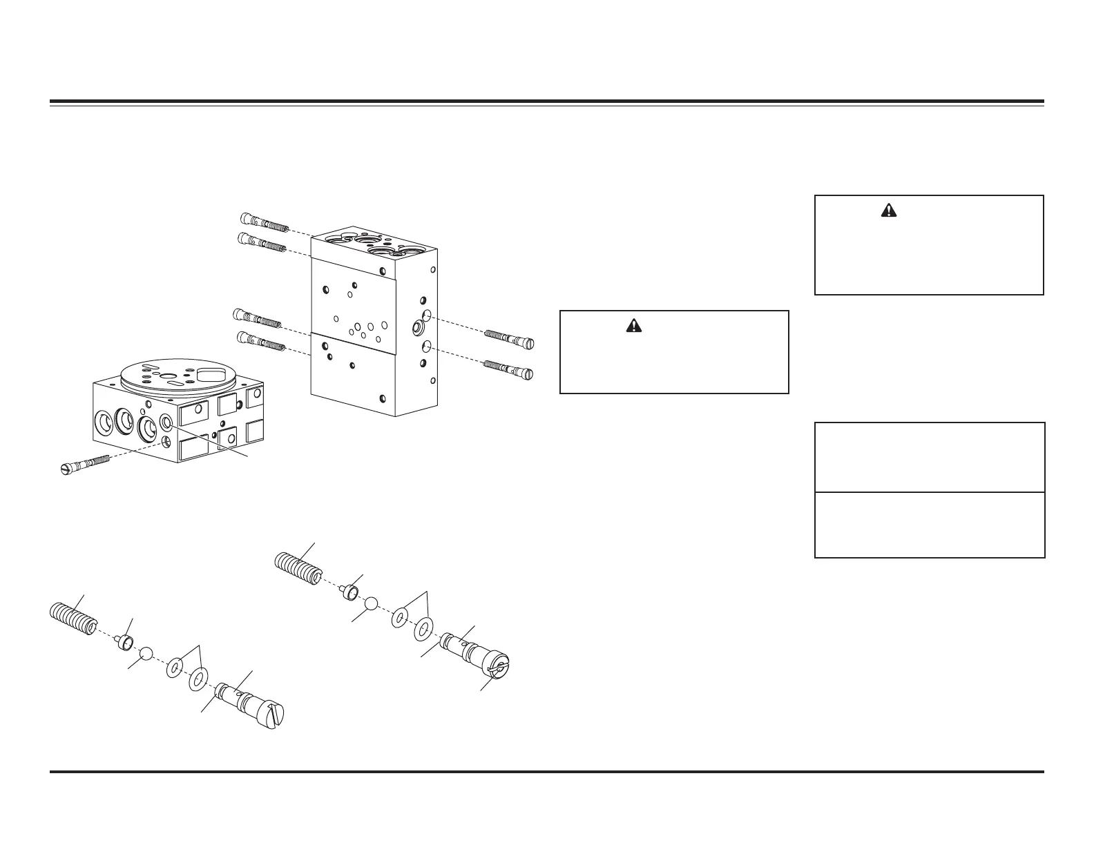
RELIEF VALVE INSPECTION AND ADJUSTMENT
Relief valves B and components are not interchangeable with A and C. The
stem is marked with a drill point in the screwdriver slot for identification.
Assembly A & C
1/4" Ball
.125 Ø Hole
Valve Stem
Seat
O-Rings
Spring
Spacer
Valve Stem
Assembly B
Drill Point
Identification
Mark
7/32" Ball
.115 Ø Hole
Valve Stem
Seat
O-Rings
Spring
Spacer
Valve Stem
PS
B
Base-End
Relief Valves
C
Pump Relief Valve
Pressure
Test Port
DS
A
Rod-End
Relief Valves
PS
DS
A (Qty 2)
B (Qty 4)
C (Qty 1)
1-1/4
1-1/4
2-1/2
3700
4600
2250*
Relief
Valve
Approx.
Pressure
(psi)
# of Turns
Out (ccw)
from
Fully Seated
* See the Pump Pressure Test
Section for details.
 Loading...