Lit. No. 27366, Rev. 01 February 15, 2008
54
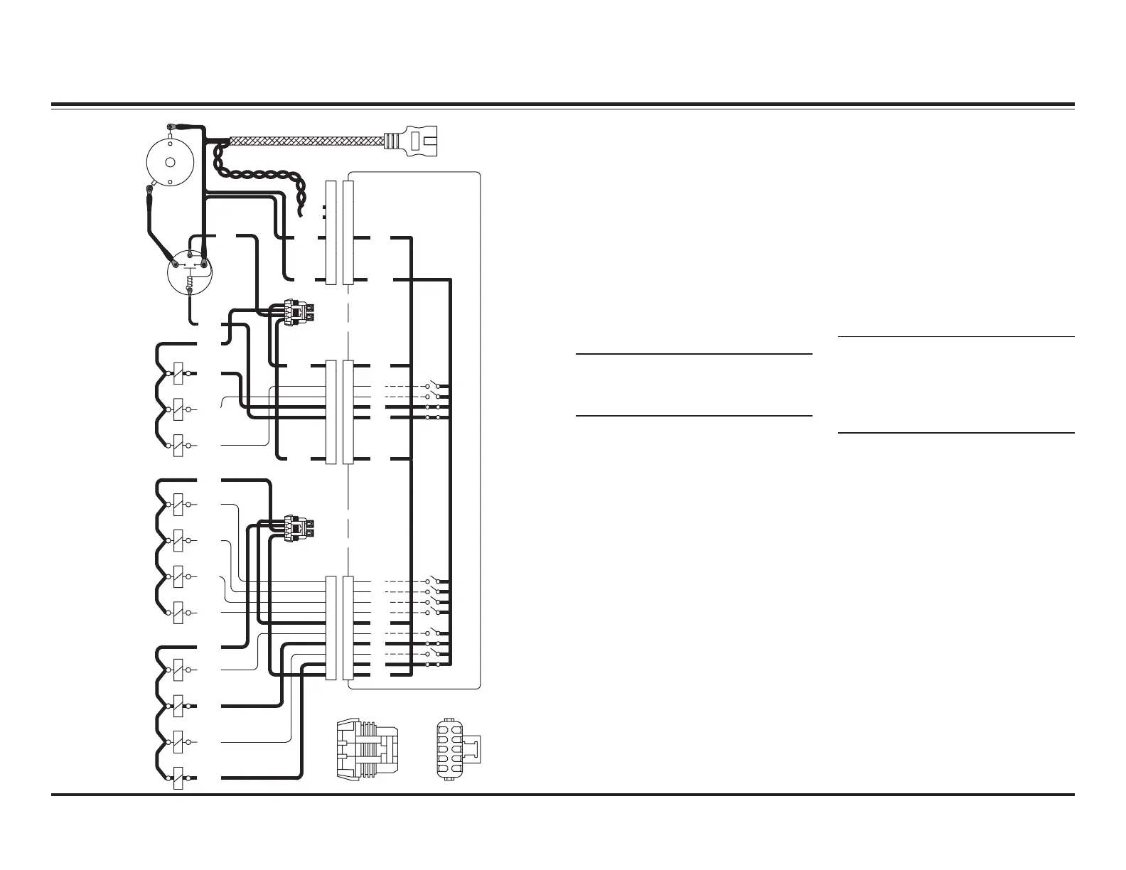
LEFT RETRACT – ELECTRICAL
System Response
1. By activating the WING function
on the left side of the cab
control, the control sends a
signal to the Plow Module to
complete the ground path for
the electrical circuit, activating
the motor relay and solenoid
cartridge valves S1, S4 & S6.
The wing mode toggles between
extend and retract.
NOTE: See the System Overview –
Controls Section for operation
information.
Plow Module
4 Amp Fuse: Motor
Relay
4 Amp Fuse: S1, S2, S3
Pump
Motor
Motor
Relay
GG
A
A
A
B
C
E
D
F
B
C
D
E
F
H
KK
H
JJ
A
B
A
GG
B
D
C
F
E
D
B
C
F
E
H
KK
H
JJ
4 Amp Fuse: S8, S9,
S10, S11
4 Amp Fuse: S4, S5,
S6, S7
Wire Side View
10-Pin Connector
BB
A
C
A
HH
D
C
F
G
EE
D
C
F
G
K
J
K
J
WHT
TAN
BLK
RED
RED
RED
S1
S2
S3
BLK
RED
RED
WHT
GRN
BLU
RED
12V
COM
12V
M/R
S2
S3
S1
12V
S10
S9
S8
S11
S7
S6
GRY
RED
WHT
GRN
ORN
RED
BRN
YEL
S4
S5
BLK
TAN
S9
S8
S5
12V
S10
S11
S7
S6
S4
12V
E
D
B
C
A
F
G
J
H
K
+
–
BLK
RED
2. Hydraulic fluid from the pump
flows through activated S4 into
the rod end of the DS ram,
causing it to retract.
3. The retracting DS ram pushes
the hydraulic fluid out of its base
end, through activated S6 & S1
and back to the reservoir.
NOTE: Battery voltage is supplied
to the Plow Module, the motor
relay and the 11 solenoid coils
when the snowplow is connected
to the vehicle.
 Loading...