17
5.3.1 Power supply, 4 ... 20 mA current loop
The model T16 is a 2-wire, powered temperature transmitter. Depending on the version, it
can be supplied with various types of power supply.
With flexible leads we recommend the use of crimped connector sleeves.
The integrated reverse polarity protection (wrong polarity on the terminals ⊕ and ⊖)
prevents the transmitter from being damaged.
Maximum values
■
Model T16.x-ZZ: DC 35 V
■
Model T16.x-AI: DC 30 V
■
Model T16.x-AC: DC 30 V
■
Model T16.x-AN: DC 35 V
■
Model T16.x-AE: DC 35 V
Minimum terminal voltage
DC 10 V
The load must not be too high, as otherwise, in the case of relatively high currents, the
terminal voltage at the transmitter will be too low.
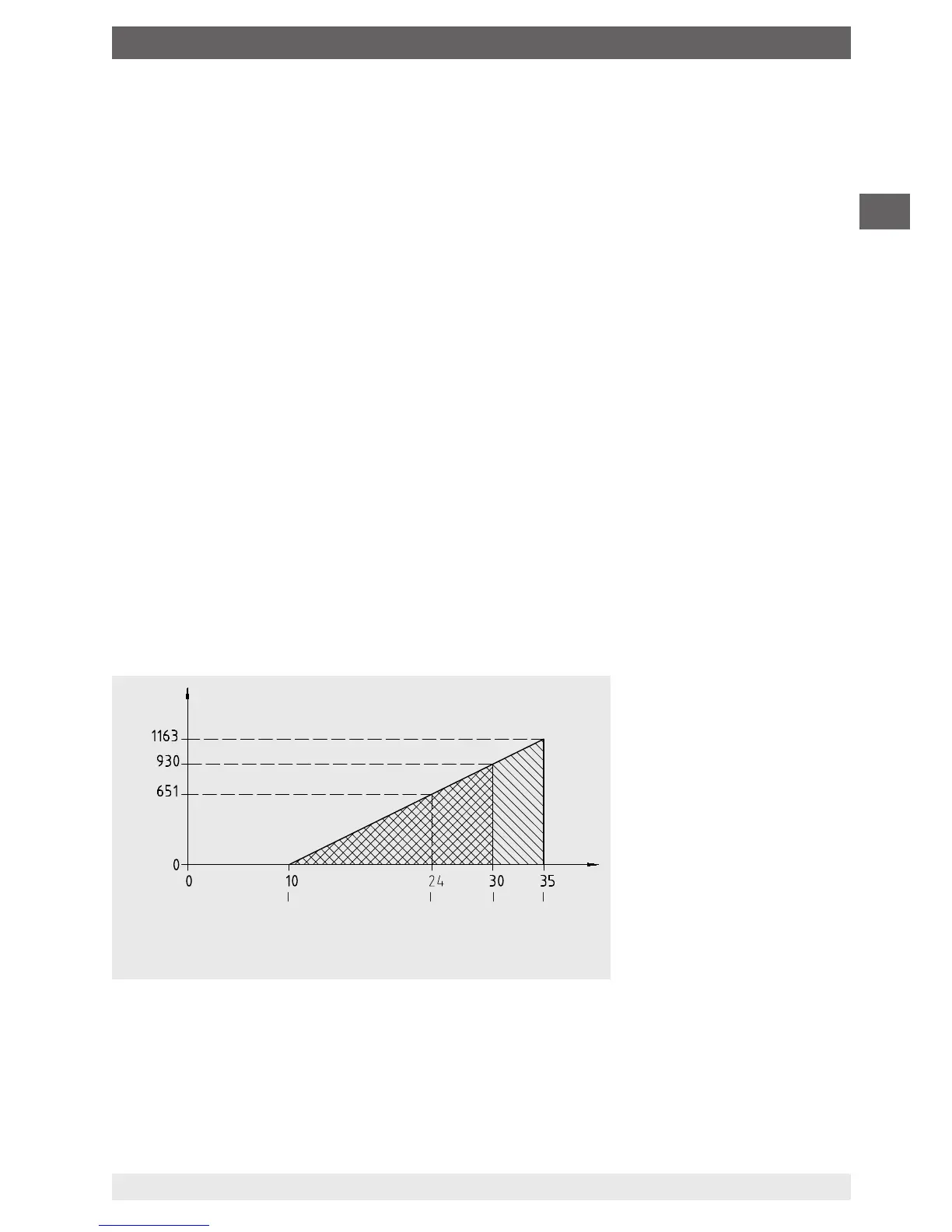
Maximum permissible load depending on the supply voltage
Load diagram
Voltage U
B
in V
Load R
A
in Ω
14222396.01
Min. voltage
Operating
voltage
Ex instru-
ments
Non-Ex
instruments