21
WILDEN PUMP & ENGINEERING, LLCWIL-10230-E-02
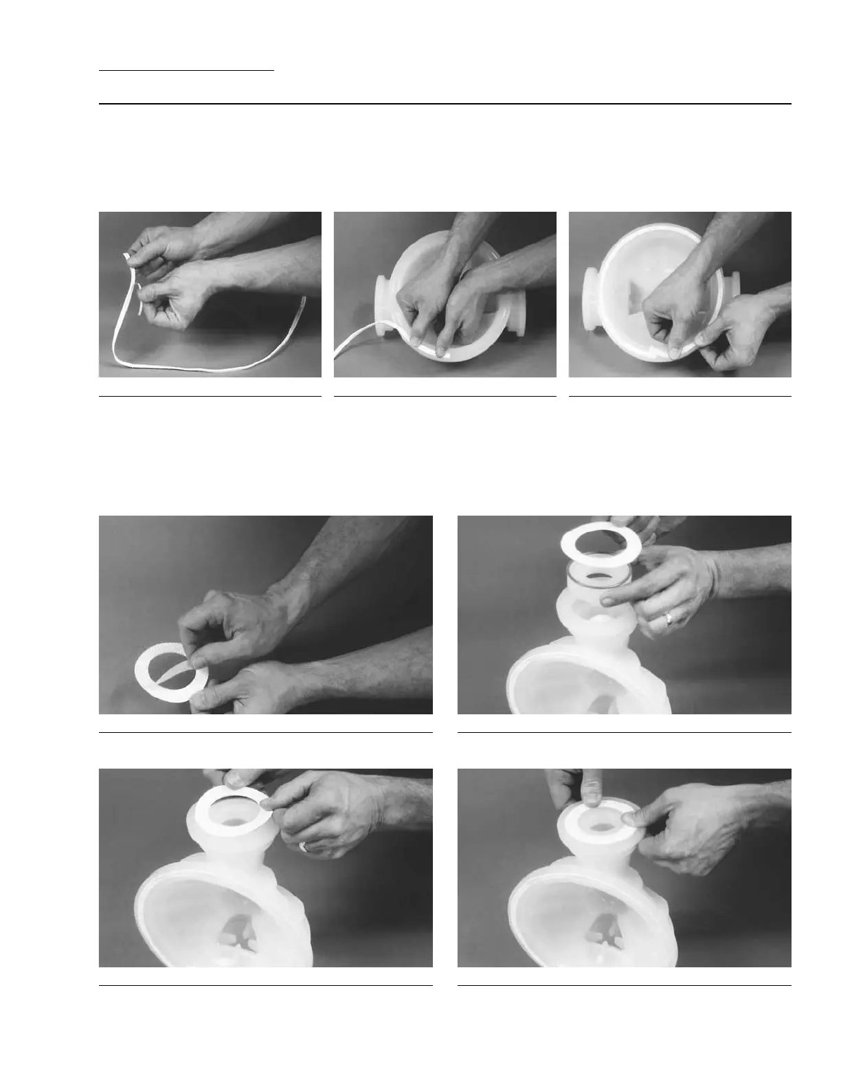
Step 1. Figure 1
Gently remove the adhesive covering
from the back of the PTFE tape. Ensure
that the adhesive strip remains attached
to the PTFE tape.
Step 2. Figure 2
Starting at any point, place the PTFE
tape in the center of the diaphragm
bead groove on the liquid chamber and
press lightly on the tape to ensure that
the adhesive holds it in place during
assembly. Do not stretch the tape during
placement in center of diaphragm bead
groove.
Step 3. Figure 3
The ends of the tape should overlap
approximately 13 mm (1/2”). Proceed to
install the PTFE tape on the remaining
liquid chamber.
Only PTFE-fitted T8 PVDF and polypropylene pumps come
standard with expanded PTFE Gasket Kits (P/N 08-9503-
99 for PVDF and 08-9502-99 for polypropylene). Carefully
prepare sealing surfaces by removing all debris and foreign
matter from diaphragm bead and all mating surfaces. If neces-
sary, smooth or deburr all sealing surfaces. Mating surfaces
must be properly aligned in order to ensure positive sealing
characteristics.
SECTION 8D
GASKET KIT INSTALLATION
Step 4. Figure 4
Carefully remove the protective covering from the back of
the PTFE gasket attached to tape.
Step 5. Figure 5
Install the valve ball, valve seat and o-ring.
Step 6. Figure 6
Center the gasket so that it evenly covers the o-ring and
seat areas.
Step 7. Figure 7
Gently apply pressure to gasket to ensure the adhesive main-
tains a positive seal to stay in place during pump assembly.
PVDF
PVDF AND POLYPROPYLENE