7
WILDEN PUMP & ENGINEERING, LLCWIL-10230-E-02
SECTION 5E
PERFORMANCE CURVES
A8 PLASTIC ACCU-FLO™
RUBBER/TPE-FITTED
Height ..................................770 mm (30.3”)
Width ...................................490 mm (19.3”)
Depth ..................................333 mm (13.1”)
Est. Ship Weight ........Polypropylene 34 kg (75 lbs)
PVDF 43 kg (95 lbs)
Air Inlet ....................................19 mm (3/4”)
Inlet ............................................51 mm (2”)
Outlet .........................................51 mm (2”)
Suction Lift ...........................6.1 m Dry (20’)
8.5 m Wet (28’)
Displacement / Stroke ..... 0.55 gal. (2.08 l)
1
Max. Flow Rate ...............420 lpm (111 gpm)
Max. Size Solids .....................6.4 mm (1/4”)
1
Displacement per stroke was calculated at 4.8 bar
(70 psig) air inlet pressure against a 2 bar (30 psig)
head pressure.
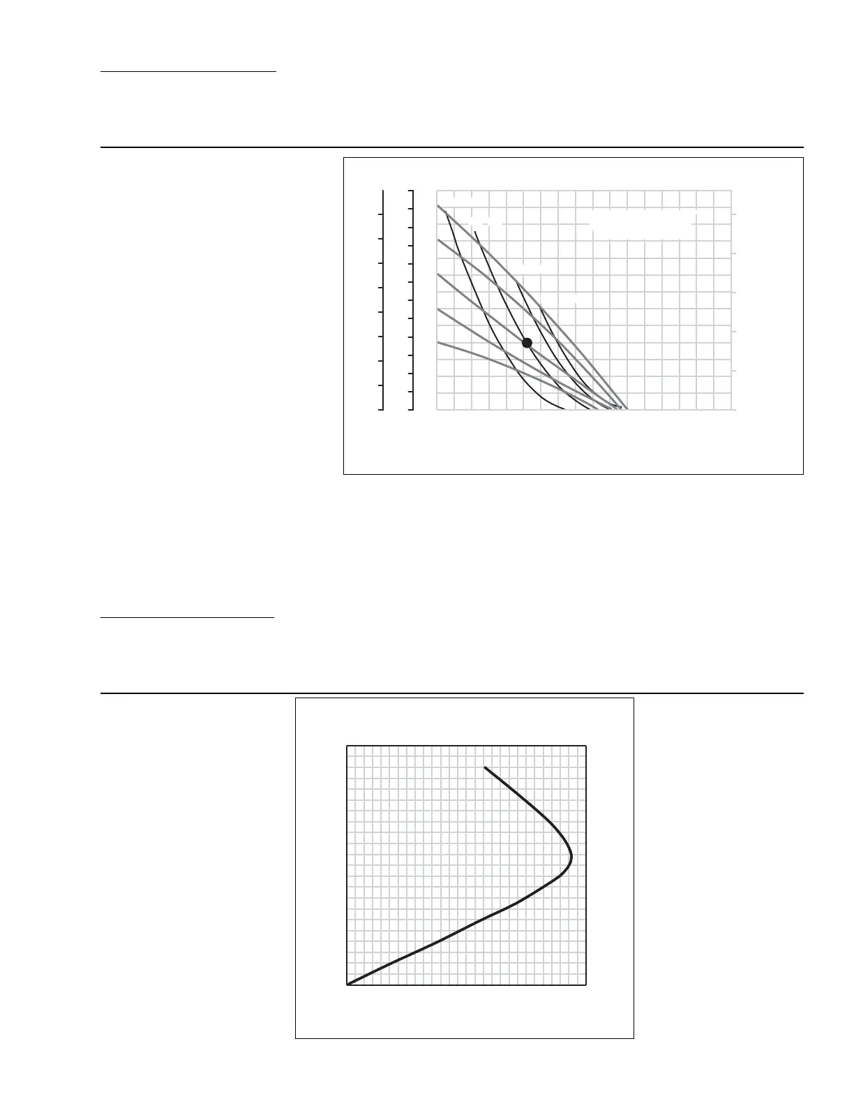
Example: To pump 197 lpm (52 gpm) against
a discharge pressure head of 2.7 bar (40 psig)
requires 5.5 bar (80 psig) inlet air pressure,
68 Nm
3
/h (40 scfm) air consumption and a
pump speed of 108 strokes/minute. (See dot
on chart.)
Caution: Do not exceed 8.6 bar (125 psig) air
supply pressure.
Flow curves are for “optimal speed” conditions only. The “optimal speed” is that speed which
provides the maximum flow under a particular air and fluid pressure condition. The optimal speed
varies for different fluid and air pressures. Recommendations for optimal speed can be found on
the right side of the flow curve.
Flow rates indicated on chart were determined by pumping water.
For optimum life and performance, pumps should be specified so that daily operation parameters
will fall in the center of the pump performance curve.
Note: TPE suction lift is approximately half that of rubber-fitted.
AIR CONSUMPTION
(SCFM) [Nm
3
/h]
20 40 60 80 100 120 140 160
PSIG
20
40
60
80
100
120
FEET
0
25
50
75
100
125
150
175
200
225
250
275
300
BAR
0
1
2
3
4
5
6
7
8
Optimal Speed
0.4
0.5
0.6
0.7
0.8
0.9
(20) [34]
(40) [68]
(60) [102]
(80) [136]
GPM
[LPM] [76] [151] [227] [303] [378] [454] [530]
Discharge Pressur
e
[606]
Sec / Stroke
Interval
[150]
[120]
[100]
[86]
[75]
[67]
[SPM]
Water Discharge Flow Rates
SECTION 5F
70/30 OPERATING CONDITION
A8 PLASTIC ACCU-FLO™
RUBBER/TPE-FITTED
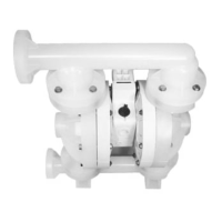
A8 Plastic Accu-Flo™ Rubber / TPE-Fitted
@ 70 / 30 operating condition
10 20 30 40 50 60 70
Speed
0
20
40
60
80
100
120
140
160
180
200
220
GPM
[LPM] [114] [151] [189][38] [76] [227] [265]
SPM
Water Discharge Flow Rate
This curve demonstrates the flow
created when the stroke rate is modi-
fied under a static air and fluid pres-
sure condition. This curve can be
applied to different pressure conditions
to estimate the change in flow due to
stroke rate.