90
6 Conditions of use and installation
The machine operator must arrange for the site preparatory work. This should be carried out by
approved contractors in accordance with general and local regulations. WMF customer service
technicians are only permitted to connect up the machine to the prepared connections. They are
not authorised to carry out plumbing or wiring work on site and will not be responsible for such
work.
Rated power 3.3 kW 6.3 kW
Connecting cable, site supply*
3 x 1.5
2
5 x 2.5
2
Fuse, site supply
1 x 16 A 3 x 16 A
Mains voltage tolerance
230 V / 400 V + 6 % - 10 %
Power cut < 50 ms does not affect machine operation
Water feed line
TW 15 (DN 15 min. DN 6 or 1/4") with main shutoff valve
and dirt filter installed by customer,
min. 0,2 MPa flow pressure at 2 l/min, max. 0,6 MPa
max. inlet temperature 35°C
Water quality If the local water has a carbonate hardness over 5° a
WMF water filter must be fitted in the supply line.
Water drain line
Hose, DN 19, minimum gradient 2 cm/m
Ambient temperature
+ 5°C to + 35°C (drain water system in case of frost)
Max. humidity 80 % rel. humidity without dewing; do not spray ma-
chine with water; do not use machine out of doors
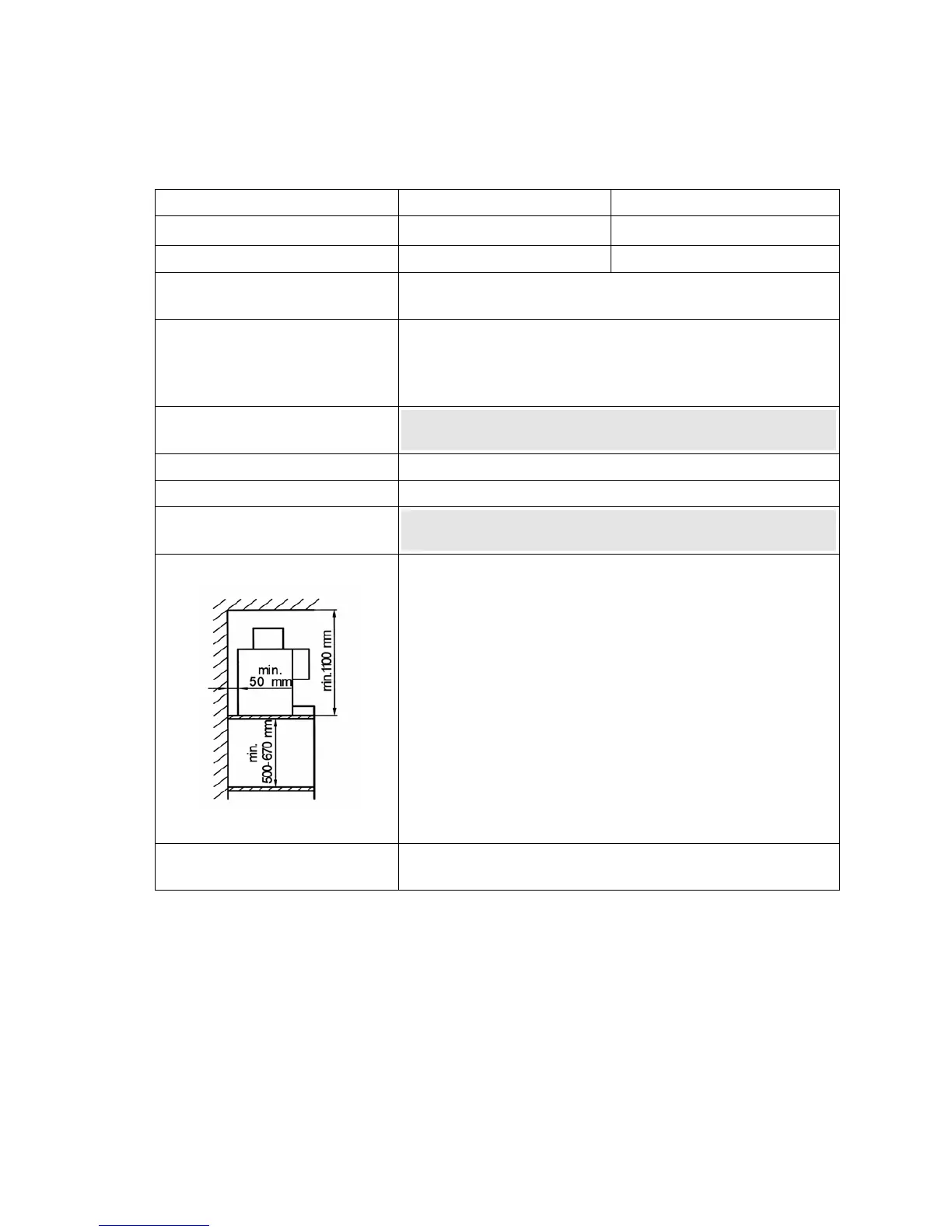
Installation clearance
When operating for service and safety reasons, the machine
should be installed with clearance of not less than 50 mm
from the back and sides from the building or non-WMF
components. A clear height of 1100 mm from the top of the
supporting surface should be ensured. The height of the sup-
porting surface from the floor surface should be not less than
700 mm and not more than 900 mm. Use of the area below
the machine for accessories (e.g. water filter or grouts sepa-
rator) requires a clear height of between 500 and 670 mm,
depending on the configuration and local installation condi-
tions. If the machine connections are to be routed down
through the counter, remember also to allow space for the
connections. These may restrict the available space below
the machine.
Water filter installation di-
mensions W x H x D
Standard: 250 x 500 x 400 mm
Jumbo: 290 x 670 x 420 mm
* The on-site electrical system must comply with IEC 364. An e.l.c.b. switch with 30 mA rated fault current to
EN 61008 should be installed upstream of the unit for increased safety. An earthed socket outlet must be in-
stalled near the unit for one-phase connection. A 5-pole CEE/CEKON socket outlet to EN 60309 must be in-
stalled for three-phase connection. If the mains power cable of this unit is damaged, it must be replaced by our
customer service engineer or a similarly qualified person. If the machine is permanently connected on site, a
disconnecting device (master switch) to EN 60947 acting on all poles and with a contact gap of at least 3 mm
must be installed upstream. The disconnecting device is also recommended for flexible connection. The mains
power cable must not be allowed to come into contact with hot parts of the machine. Master switch and socket
outlet are part of the on-site installation. The machine must not be installed with permanent on-site connection
when mounted on a trolley.
 Loading...