22
2
1
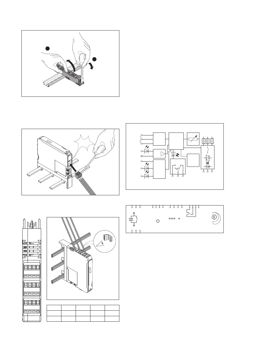
Connecting the motor output in the
main circuit
The motor output is connected using a 3-pole plug
connector (included in the scope of delivery).
Click
4. Connecting the control wires
X5 U R L
X4 MAN Res AUT
T
E
X3 95 96 97
The 24V DC control supply voltage and control voltage
inputs must be operated with power supply modules
according to DIN 19240 (max. 5% residual ripple)!
In order to avoid inductive or capacitive coupling of
noise emissions where long control wires are used, we
recommend the use of shielded wires.
If you want to clamp two conductors under one
terminal point, you must use conductors with the
same conductor cross section!
5. Functions
Block diagramm
MAN
RES
AUT
T
T
E
Us
L
R
Reset 2
Reset
Auto
-
Reset
24
V DC
24 V DC
97
2/T1
96
4/T2
95
6/T3
Logic
µP
L1 L2
L3
& Error
reset
EPLAN-symbol
MOTUS®ContactronControl
Set /
Reset
R L Err PWR
9 A
max.
x1
x2 x5 x4 x3
1/L1 3/L3 5/L3 Us
T
R
L MAN RES AUT
95
2/T1
4/T2
6/T3
96 97
T
E
Visualisation – Status-LEDs
The MOTUS visually indicates its operating status via
four LEDs. The functions of the LEDs are based on the
NAMUR recommendation NE44.
ɴ When the control supply voltage is connected, all
LEDs light up once as a LED test.
ɴ A green LED (PWR) indicates that the control supply
voltage is “OK”.
ɴ Left or right rotation of the drive is indicated by a
corresponding yellow LED (L or R).
ɴ An error is indicated by a red LED (Err).
3.
T
RL
MAN RES AUT
Us
T
E
97 96 95
T