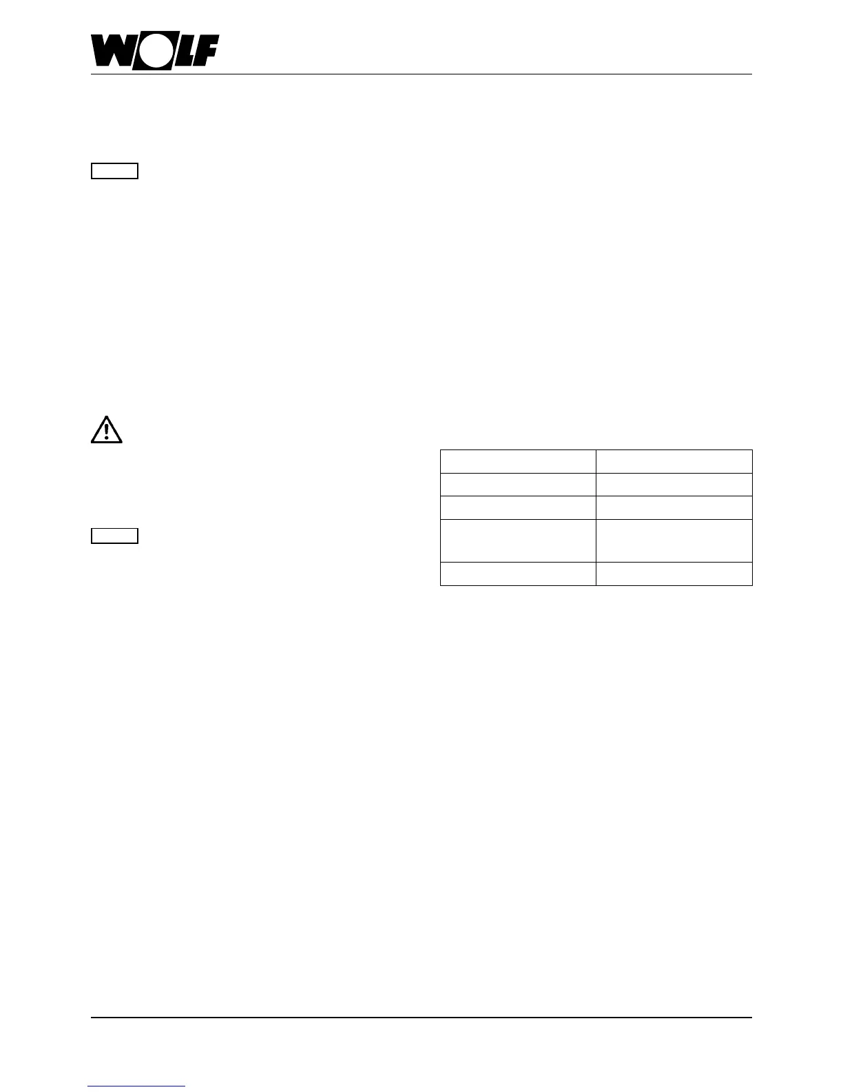
50 3062555_201804
Fluegastemperaturelimiter
The electronic ue gas temperature limiter switches the oil
condensingboileroffwhentheuegastemperatureexceeds
110 °C.
Theappliancewillrestartoperationwhenthe
restbuttonispressed.Itisimportanttondout
whytheappliancedeactivatedbeforeresetting
the boiler. Resetting the boiler when the ue
gas temperature is too highcan destroy the
uegassystem.
Note
Calculatingthebalanceduelength
The calculated length of the air/ue gas routing system or
standard ue is derived from the straight pipe length and
the length of any pipe bends. In this calculation, a 87° bend
or a 87° tee is calculated as being 2 m and a 45° bend as
being 1 m.
For boilers with a rated heating output above 50 kW, a clear-
anceofat least1.0 mbetweenthe ueoutlet andthe roof
surface is required.
Example:
Lengthofstraightbalancedue1.5m
Inspectiontee87°=2m
2x45°bends=2x1m
L=1.5m+1x2m+2x1m
L=5.5m
Component Lengthtobeallowedfor
87° bend 2m
45° bend 1m
87° tee with
inspection port
2m
Straight pipe Corresponding to length
Table: Pipe length calculation
Connectiontotheair/uegasroutingsystem
It must be possible to inspect the entire cross-section of the
ues.Therefore,installanappropriatecleaningand/orinspec-
tion port inside the boiler room; agree suitable arrangements
withthelocaluegasinspector.
Flue connections are created using female connections and
gaskets. Always arrange female connections against the di-
rectionofthecondensateow.
Install the air/ue gas routing system with a
slopeofatleast3°(6cm/m)towardsthegas
condensingboiler.Installspacerclipstosecure
inplace(seeinstallationexamples).
Intheworstcasescenario,alesserslopeofthe
air/uegasroutingsystemmayleadtocorro-
sionoroperatingfaults.
Always bevel or deburr cut flues to ensure
gas-tight installation of pipe joints. En-
sure that gaskets are fitted correctly.Re-
move all contamination prior to installation.
–nevertdamagedparts.
Note
28.Technicalinformation