EE--SSeerriieess WWaallll OOvveenn
EE--SSeerriieess WWaallll OOvveenn
Component Access & Removal
4-6
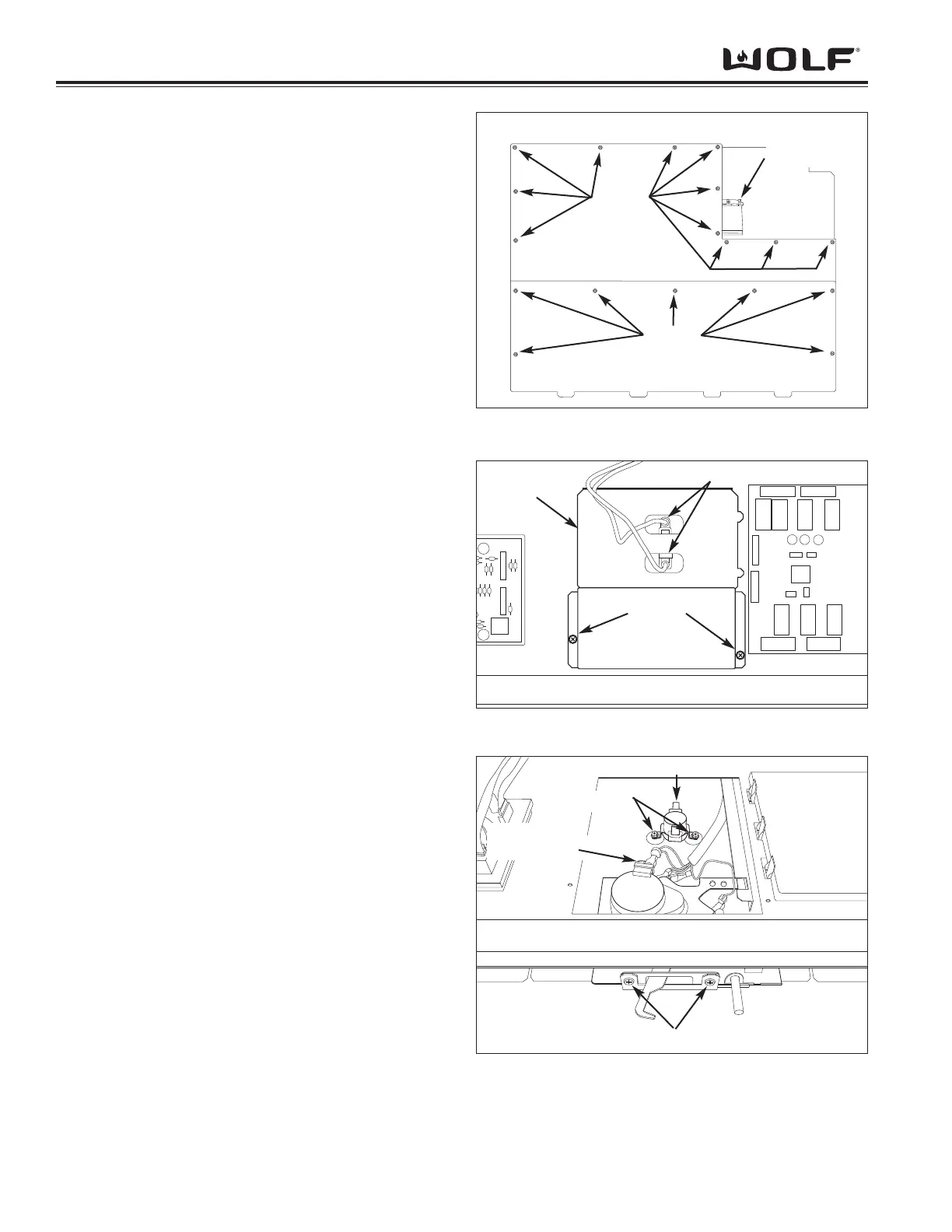
Top Front and Rear Panel Removal
The top panels are removed by extracting the screws
around outside edges of the panels. (See Figure 4-11)
Upper Motorized Door Latch Assembly Removal
The motorized latch is secured with screws to a bracket
at the front of module pan. The latch assembly consists
of the motorized latch and a plunger type switch.
To remove the motorized latch, open oven door, remove
vented face plate, control panel and top front panel:
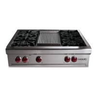
1. Disconnect the electrical leads from upper thermo-
stat switch. (See Figure 4-12)
2. Extract the screws from front of latch cover. Lift
latch cover up until tabs slide out from under the
module pan and remove.
3. Disconnect the wire leads from motor terminals and
switch assembly.
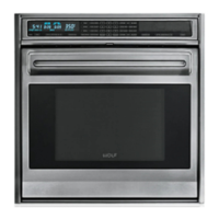
4. Extract screws from front of unit securing motorized
latch to the module pan. (See Figure 4-13) Slide
assembly back and lift out of slots in module pan.
5. The micro-switch for plunger switch is removed by
extracting the screw securing it to the motorized
latch assembly and disconnecting electrical leads.
Lower Motorized Door Latch Assembly Removal
1. Extract screws from front of unit securing motorized
latch to the module pan. Slide assembly back and
lift out of slots in module pan.
2. The micro-switch for plunger switch is removed by
extracting the screw securing it to the motorized
latch assembly and disconnecting electrical leads.
Upper Thermostat Switch Removal
The upper thermostat switch is located behind the
motorized latch assembly and under latch cover. The
thermostat is secured with screws to the mounting
plate.
To remove the upper thermostat switch, open oven
door, remove vented face plate, control panel and top
front panel:
1. Disconnect the electrical leads from upper thermo-
stat switch. (See Figure 4-12)
2. Extract the screws from front of latch cover. Lift
latch cover up until tabs slide out from under the
module pan and remove.
3. Extract the screws securing the thermostat to the
module panel floor and remove. (See Figure 4-13)