EE--SSeerriieess WWaallll OOvveenn
EE--SSeerriieess WWaallll OOvveenn
Component Access & Removal
4-13
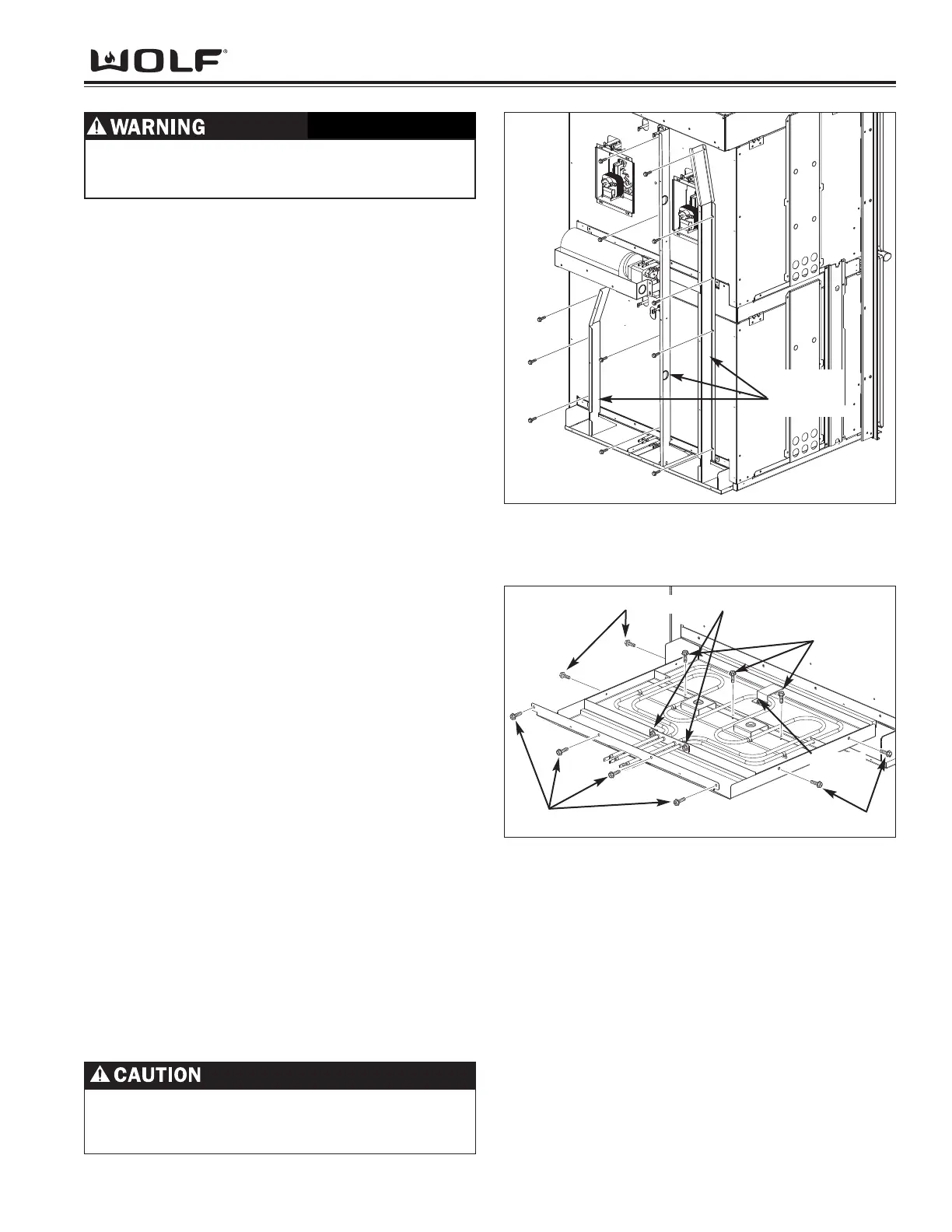
Divider Channels
Disconnect and remove any wiring which is routed
through the channels. Now, extract the screws which
secure the channels to the unit and remove.
(See Figure 4-30).
NOTE: When disconnecting the wiring, make sure to
mark the wire locations. This will ensure proper place-
ment when reinstalling.
Bake Element Assembly Removal
The bake element assemblies are located under each
oven cavity and are secured with screws to the back of
the oven frame.
1. Remove the rear panel (See Rear Panel Removal)
and divider channels (See Divier Channels).
NOTE: It may be necessary to disconnect some of the
wiring and cut some of the wire ties from the electri-
cal wiring in order to gain more space for bake ele-
ment to be removed. Replace wire ties when
reassembling.
NOTE: When disconnecting the wiring, make sure to
mark the wire locations. This will ensure proper
placement when reinstalling.
2. If replacing the upper bake element in a double
oven you will need to remove lower cooling fan
(See Lower Cooling Fan and Cover Removal).
3. Disconnect wire leads from bake element terminals.
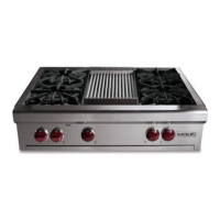
4. Extract the screws from bake pan assembly and
pull the bake element assembly from unit.
(See Figure 4-32).
5. Remove element by extracting two mounting
screws securing element to inner pan and the
screw from element retaining clamp. Next, remove
the three screws securing the element bracket.
6. The inner pan is separated from the bake element
pan by extracting the screws from the sides of the
element pan.
NOTE: The wiring may need to be routed around the
bake element to fully remove it from the unit. Return the
wires to their orginal routing when reassembling.
Figure 4-32. Bake Element Removal.
Figure 4-31. Divider Channels Removal.
Divider
Channels
Screws
Inner Pan Screws
Inner Pan Screws
Element Mounting Screws
Screw
The insulation around the hidden bake element is
very fragile. Removal of the bake element should
be done with great care.
Element Bracket Screws
TO AVOID ELECTRICAL SHOCK, POWER TO THE
UNIT MUST BE DISCONNECTED BEFORE
ATTEMPTING THE FOLLOWING REPAIRS.