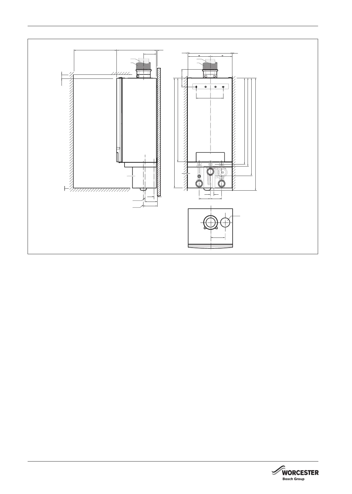
DIMENSIONS OF BOILER
6 720 648 726 (2011/07)
18
Fig. 7 Dimensions and connections WITH pump group (dimensions in mm)
1) The pump group is an accessory which has to be ordered separately.
CDO Condensate drain outlet; Ø 24 mm O/D
CHF CH (boiler) flow; G1½’’ union nut with female thread
CHR CH (boiler) return; G1½’’ union nut with female thread
CS Cap (DO NOT remove)
FGC/AIC Flue gas/air intake connection: Ø 80/125 for GB162-65 and Ø 100/150 for GB162-80/100
GAS B Gas connection to boiler; G1’’ female thread
GAS P Gas connection to pump group; Rp1’’ female thread
PF Pump group flow; G1½’’ male thread, flat seal
PR Pump group return; G1½’’ male thread, flat seal
The servicing clearances required are:
• in front: 50 mm
• below: 0 mm (250 mm with pump group)
• right side: 0 mm
• left side: 0 mm
• above: 30 mm.
The position selected for installation MUST allow
adequate space for servicing in front of the boiler:
• in front: 550 mm
• below: 350 mm
• right side: 0 mm
• left side: 0 mm
• above: 40 mm.
CDO
1280
980
1003
1030
1186
1310
135
103.5
520
300
140
130 130
39
35
138
162
465
6
152
FGC
AIC
FGC
AIC
CHF CHRGAS B
PF PRGAS A
CDO
CS
PF/PR
550
40
0
0
0
1)
1)
6 720 648 726-007.1TD
 Loading...


