INSTALLATION
6 720 648 726 (2011/07)
26
8.3 FLUE INSTALLATION
8.3.1 SITING THE FLUE TERMINAL
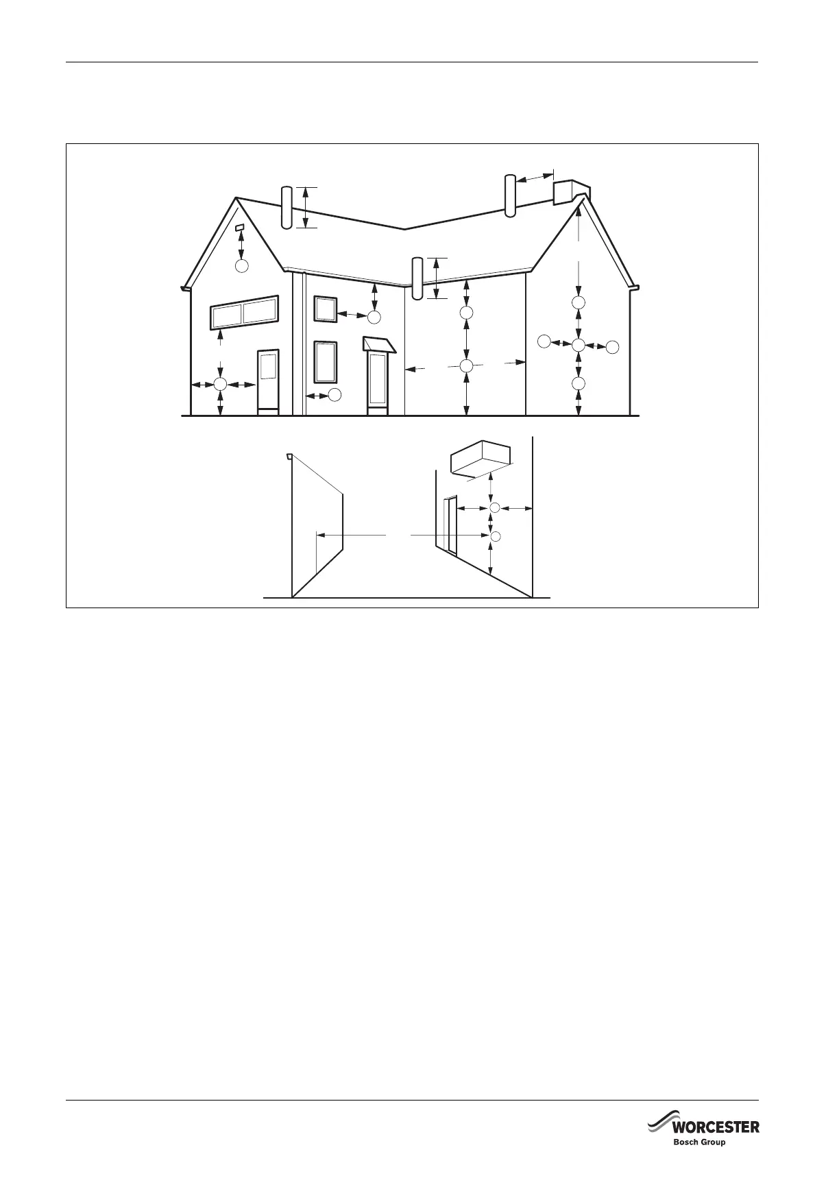
Fig. 26 Balanced flue terminal position
Terminal position Minimum spacing:
A Directly below, above or alongside an opening window, air vent or other ventilation opening 300 mm
B Below guttering, drain pipes or soil pipes 200 mm
C Below eaves 200 mm
D Below balconies or a car port roof Not recommended! 200 mm
E From vertical drain pipes or soil pipes 150 mm
F From internal or external corners 300 mm
G Above adjacent ground, roof or balcony level 300 mm
H From a surface facing the terminal 600 mm
I From a terminal facing a terminal 1200 mm
J From an opening in a car port (e.g. door or window) into dwelling. Not recommended! 1200 mm
K Vertically from a terminal on the same wall 1500 mm
L Horizontally from a terminal on the wall 300 mm
M Adjacent to opening 300 mm
N Above intersection with roof 300 mm
O From a vertical structure on the roof 500 mm
The flue for installations in excess of 70 kW must be
installed in accordance with the recommendations of
IGE UP10.
Pluming will occur at the terminal so terminal positions
where this could cause a nuisance should be avoided.
The air supply and the flue gas exhaust must meet the
applicable general regulations. Please consult the
instructions provided with the flue terminal kits prior to
installation.
The boiler MUST be installed so that the terminal is
exposed to external air.
It is important that the position of the terminal allows
the free passage of air at all times.
Minimum acceptable spacing from the terminal to
obstructions and ventilation openings are specified in
fig. 26.
A
F
M
G
M
B,C
F
F
B,C
K
G
K
K
G
C
L
L
A
N
N
O
E
FJ
K
G
D
H, I
6 720 648 726-026.1TD
 Loading...


