COMMISSIONING
6 720 648 726 (2011/07)
55
10.2.9 MEASURING THE FLUE GASES CO
2
EMISSIONS
B Open at least 2 thermostatic radiator valves. Do not
switch on the boiler.
B Push on the control panel to open it (Æ fig. 68,
page 40).
B Switch off the heating system by pressing the mains
switch of the BC10 basic controller (Æ fig. 90, [1]).
B Remove the cover from the flue gas measuring point
[1].
B Connect the flue gas analyser to the left-hand
measuring point.
Fig. 91 Measuring the gas supply pressure
B Switch on the heating system by pressing the mains
switch of the BC10 basic controller (Æ fig. 90, [1]).
B Press and hold the "Chimney sweep" button
(Æ fig. 90, [3]) (approx. 2 seconds), until the dot in
the right-hand bottom corner of the display
(Æ fig. 90, [9]) appears. See also table 10, "Flue gas
test", page 42.
B After the "Burner" LED (Æ fig. 90, [6]) has lit up wait
for one minute until the boiler is burning at full load.
B Measure the carbon monoxide content at the flue gas
measuring point (Æ fig. 91).
The CO values in air-free condition must be less than
400 ppm or 0.04 vol. %. Values of 400 ppm or more
indicate an incorrect burner adjustment
(Æ section 10.2.7, page 52), a dirty gas burner or heat
exchanger or burner faults.
B You must determine and remove the cause
(Æ chapter 12, page 61).
B Press the "Chimney sweep" button (Æ fig. 90, [3]) to
clear the reading. See also table 10, "Flue gas test",
page 42.
B Switch off the heating system by pressing the mains
switch of the BC10 basic controller Æ fig. 90, [1]).
B Remove the flue gas analyser and fit the cover back
onto the flue gas measuring point (Æ fig. 91, [1]).
B Switch on the heating system by pressing the mains
switch of the BC10 basic controller (Æ fig. 90, [1]).
B Press on the control panel to close it (Æ fig. 96,
page 58).
10.2.10 CARRYING OUT A FUNCTION TEST
B During initial start-up and annual inspection and/or
needs-oriented servicing, make sure that all control,
regulating and safety devices are in full working order
and, if applicable, check them for correct adjustment.
B The gas and water circuits must be tested for leaks
(Æ sections 10.2.1 and 10.2.8).
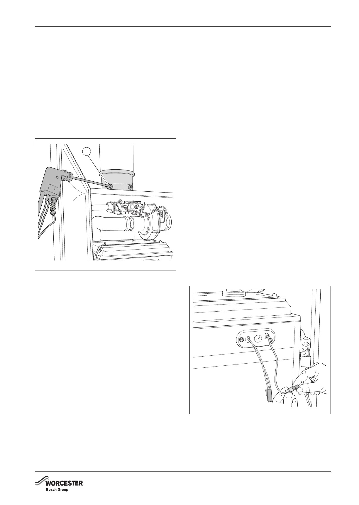
10.2.11 MEASURING THE IONISATION CURRENT
B Push on the control panel to open it (Æ
fig. 68,
page 40).
B Open at least 2 thermostatic radiator valves. Do not
switch on the boiler.
B Switch off the heating system by pressing the mains
switch of the BC10 basic controller Æ fig. 90, [1]).
B Turn the vent key through a quarter rotation to undo
the boiler door lock (Æ fig. 71, see detailed picture,
page 47).
B Push the fastener down and open the boiler door
(Æ fig. 71, page 47).
B Undo the plug and socket connection of the
monitoring cable.
Fig. 92 Removing the ionisation electrode plug and
socket connection
6 720 648 726-091.1TD
1
6 720 648 726-092.1TD
 Loading...


