SP605 Hardware User Guide www.xilinx.com 45
UG526 (v1.9) February 14, 2019
Detailed Description
User Pushbutton Switches
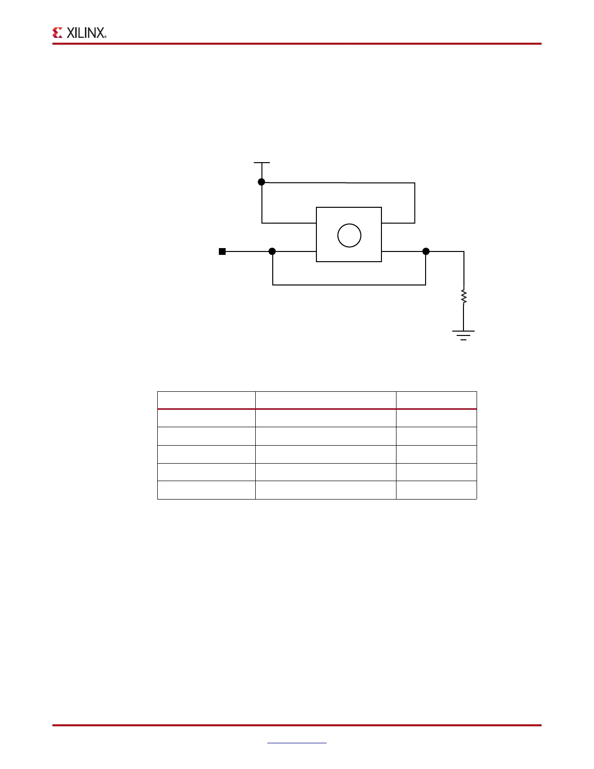
The SP605 provides five active-High pushbutton switches: SW4, SW5, SW6, SW7, and
SW8. The five pushbuttons all have the same topology as the sample shown in Figure 1-16.
Four pushbuttons are assigned as GPIO, and the fifth is assigned as a CPU_RESET.
Figure 1-16 and Table 1-24 describe the pushbutton switches.
X-Ref Target - Figure 1-1 6
Figure 1-16: User Pushbutton Switch (Typical)
Table 1-24: Pushbutton Switch Connections
U1 FPGA Pin Schematic Netname Switch Pin
F3 GPIO_BUTTON_0 SW4.2
G6 GPIO_BUTTON_1 SW7.2
F5 GPIO_BUTTON_2 SW5.2
C1 GPIO_BUTTON_3 SW8.2
H8 CPU_RESET SW6.2
VCC1V5
CPU_RESET
Pushbutton
1
1
2
4
2
SW6
R230
1.00K
1%
1/16W
3
P1
P2 P3
P4
UG526_16_092409