SP605 Hardware User Guide www.xilinx.com 49
UG526 (v1.9) February 14, 2019
Detailed Description
17. Switches
The SP605 Evaluation board includes the following switches:
• Power On/Off Slide Switch SW2
• FPGA_PROG_B Pushbutton SW3 (Active-Low)
• SYSACE_RESET_B Pushbutton SW9 (Active-Low)
• System ACE CF CompactFlash Image Select DIP Switch S1 (Active-High)
• Mode DIP Switch SW1 (Active-High)
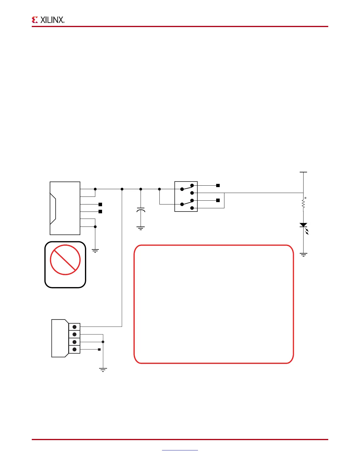
Power On/Off Slide Switch SW2
SW2 is the SP605 board main power on/off switch. Sliding the switch actuator from the off
to on position applies 12V power from either J18 (6-pin Mini-Fit) or J27 (4-pin ATX) power
connector to the VCC12_P power plane. Green LED DS14 will illuminate when the SPL605
board power is on. See 19. Power Management for details on the on-board power system.
X-Ref Target - Figure 1-20
Figure 1-20: Power On/Off Slide Switch SW2
UG526_20 _100609
N/C
12v
12v
N/C
COM
COM
1
4
2
3
6
1
2
3
4
5
NC
NC
39-30-1060
ATX Peripheral Cable Connector
can plug into J27 when SP605 is
in PC and the desk top AC adapter
(brick) is not used.
J27
J18
12V
COM
COM
5V
NC
350211-1
VCC12_P_IN
1
2
NC
NC
DPDT
VCC12_P
5
2
+
C280
330UF
16V
ELEC
1
3
4
6
SW2
1201M2S3ABE2
12
2
1
R322
1.00K
1%
1/16W
DS25
LED-GRN-SMT
CAUTION!
DO NOT plug a PC ATX power supply 6-pin connector into
the J18 connector on the SP605 board. The ATX 6-pin
connector has a different pinout than J18 and will damage
the SP605 board and void the board warranty.
DO NOT plug an auxilliary PCIe 6-pin molex power
connector into the J18 connector as this could damage the
PCIe motherboard and/or the SP605 board. J18 is marked
with a NO PCIE POWER label to warn users of the poten-
tial hazard.
DO NOT apply power to J18
and the 4-pin ATX disk drive
connector J27 at the same time as this will damage the
SP605 board.
PCIe
Power