60 www.xilinx.com SP605 Hardware User Guide
UG526 (v1.9) February 14, 2019
Chapter 1: SP605 Evaluation Board
Configuration Options
The FPGA on the SP605 Evaluation Board can be configured by the following methods:
• 3. SPI x4 Flash
• 4. Linear BPI Flash
• 5. System ACE CF and CompactFlash Connector
• 6. USB JTAG
For more information, refer to the Spartan-6 FPGA Configuration User Guide (UG380).
[Ref 2]
With the mode switch SW1 set to 01, the SP605 will attempt to boot or load a bitstream
from either the SPI X4 Flash device U32 or a user supplied SPI Flash memory mezzanine
card installed on the SPI programming header J17, depending on the SPI select jumper J46
configuration, as shown in Table 1-32. With the mode set to 00, the SP605 will attempt to
boot or load a bitstream from Linear Flash device U25 (BPI).
With the mode switch SW1 set to 10, if a CompactFlash (CF) card is installed in the CF
socket U37, System ACE CF will attempt to load a bitstream from the CF card image
address pointed to by the image select switch S1. With no CF card present, the SP605 can be
configured via the onboard JTAG controller and USB download cable as described in 6.
USB JTAG.
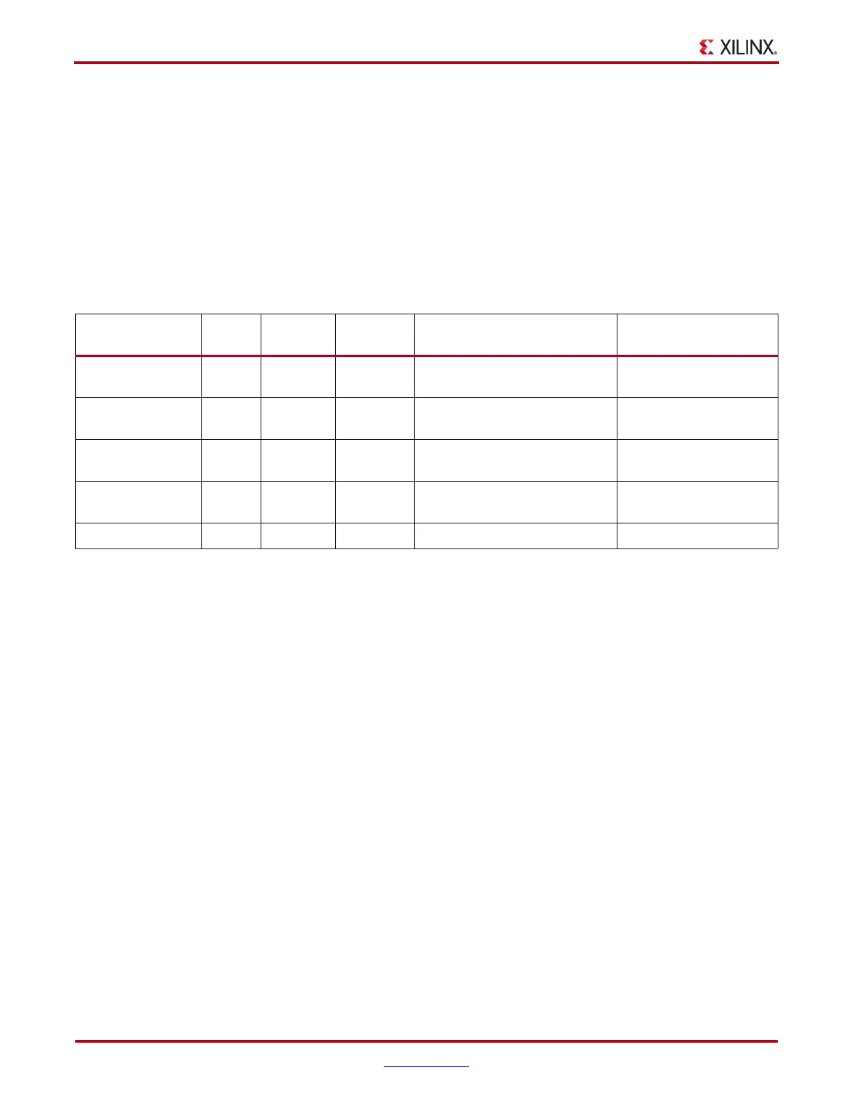
Table 1-32: SP605 FPGA Configuration Modes
Configuration
Mode
M[1:0] Bus Width
CCLK
Direction
Configuration Solution User Guide Section
Master Serial/SPI 01 1, 2, 4
(1)
Output
SPI X4 Memory U32 (J46 on), or
External SPI Header J17 (J46 off)
3. SPI x4 Flash
Master
SelectMAP/BPI
(2)
00 8, 16 Output Linear Flash Memory U25 (BPI) 4. Linear BPI Flash
JTAG
(3)
xx 1
Input
(TCK)
Xilinx Platform Cable USB
plugged into J4
6. USB JTAG
Slave SelectMAP
(2)
10 8, 16 Input
System ACE CF Controller and
CompactFlash Card
5. System ACE CF and
CompactFlash Connector
Slave Serial
(4)
11 1 Input Not Supported –
Notes:
1. Utilizing dual and quad SPI modes.
2. Parallel configuration mode bus is auto-detected by the configuration logic.
3. Spartan-6 devices also have a dedicated four-wire JTAG (IEEE Std 1149.1) port that is always available to the FPGA regardless of the
mode pin settings.
4. Default setting due to internal pull-up termination on Mode pins.