14 www.xilinx.com Virtex-6 FPGA Connectivity Kit Getting Started
UG664 (v1.4) July 6, 2011
Getting Started with the Connectivity Targeted Reference Design Demo
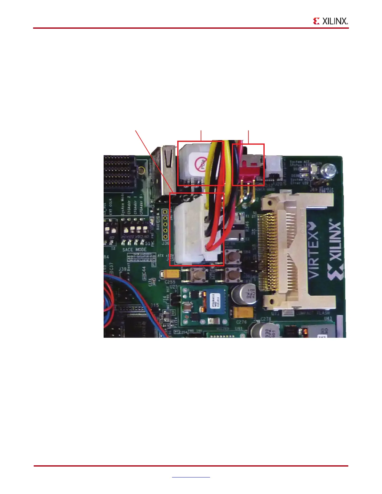
5. Hardware Setup II: Connect the power connector:
a. Turn the PC system off.
b. Connect the 12V ATX power supply’s available 4-pin disk-drive-type power
connector of the PC system to the board (J25).
Caution!
Using any power supply connector other than the 4-pin inline connector results in
damage to the PC system and the ML605 board.
c. The power switch SW2 should be switched to the ON position (away from the
bracket edge of the ML605 board) as shown in Figure 4.
6. Hardware Setup III: Insert the ML605 board into an empty PCIe slot:
a. Identify a x8 or a x16 PCIe slot on the PC motherboard.
b. Insert the ML605 board with FMC daughter card and CX4 loopback module in the
PCIe slot through the PCIe x8 edge connector.
c. On power-up, the connectivity targeted reference design for PCIe to XAUI is
loaded from the Platform Flash.
After the hardware setup is complete, the user can choose to install the Windows driver or
the Linux driver. Proceed to Install Linux Driver, page 27 to verify the design on the
Fedora 10 operating system.
X-Ref Target - Figure 4
Figure 4: 12V ATX Power Supply Connector
UG664_04_022310
J60 SW2J25

 Loading...

