14 www.xilinx.com VC7222 IBERT Getting Started Guide
UG971 (v5.0) June 12, 2014
Chapter 1: VC7222 IBERT Getting Started Guide
3. Connect the host computer to the VC7222 board using a standard-A plug to Micro-B
plug USB cable. The standard-A plug connects to a USB port on the host computer and
the Micro-B plug connects to U57, the Digilent USB JTAG configuration port on the
VC7222 board.
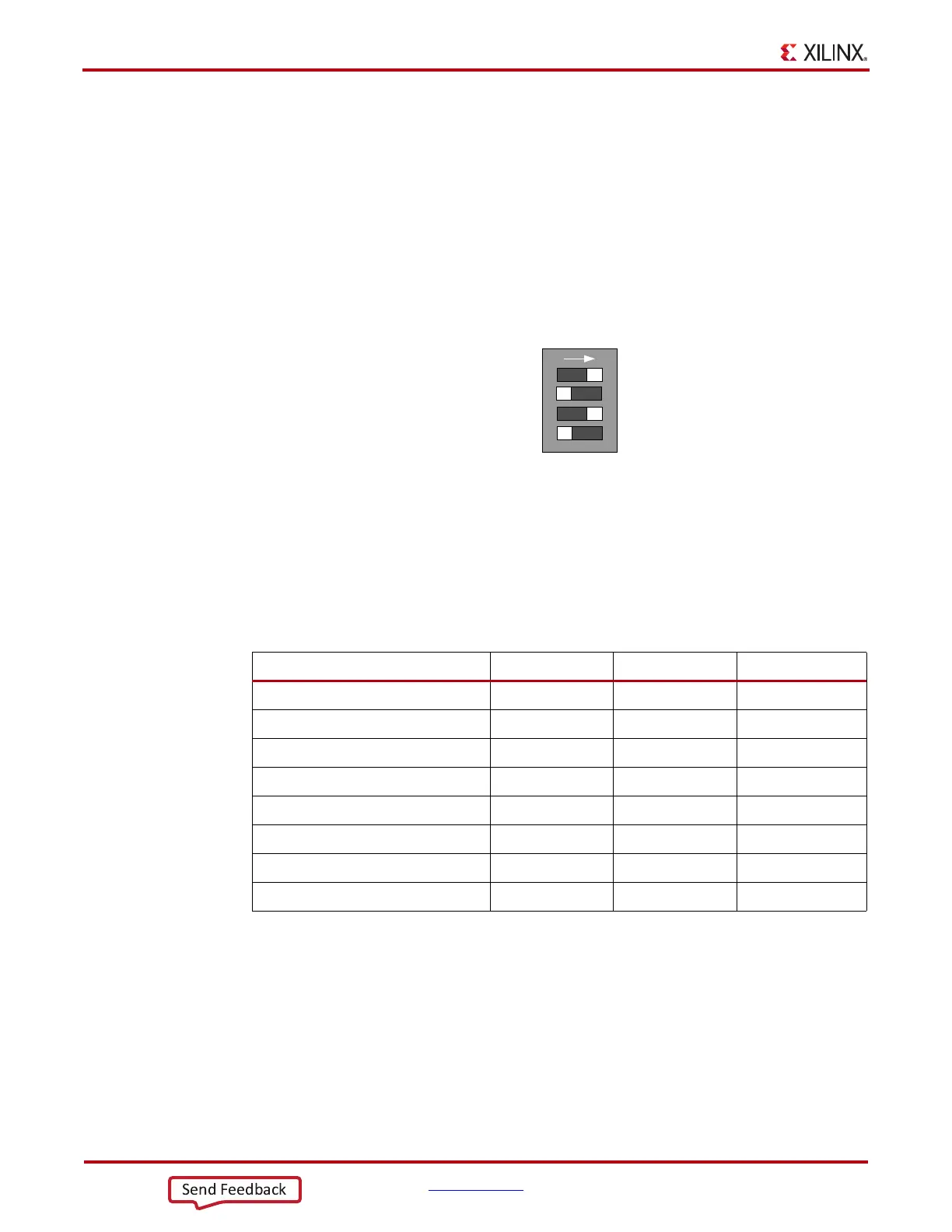
4. Select the GTH IBERT demonstration with the System ACE™ tool SD controller
SYSACE-2 CFG switch, SW8. The setting on this 4-bit DIP switch (Figure 1-9) selects
the file used to configure the FPGA. A switch is in the ON position if set to the far right
and in the OFF position if set to the far left. For the Quad 115 GTH IBERT
demonstration, set ADR2 = ON, ADR1 = OFF, and ADR0 = ON. The MODE bit (switch
position 4) is not used and can be set either ON or OFF.
There is one IBERT demonstration design for each GTH Quad on the VC7222 board, for a
total of six IBERT designs. Additional designs are provided to demonstrate the GTZ and
the USB/UART interface (details of this demonstration are described in the README file
on the SD card). All eight designs are organized and stored on the SD card as shown in
Table 1-1.
5. Place the main power switch SW1 to the ON position.
X-Ref Target - Figure 1-9
Figure 1-9: Configuration Address DIP Switch (SW8)
Table 1-1: SD Card Contents and Configuration Addresses
Demonstration Design ADR2 ADR1 ADR0
GTH Quad 113 ON ON ON
GTH Quad 114 ON ON OFF
GTH Quad 115 ON OFF ON
GTH Quad 213 ON OFF OFF
GTH Quad 214 OFF ON ON
GTH Quad 215 OFF ON OFF
GTZ Quad 300A and 300B OFF OFF ON
USB/UART OFF OFF OFF
8*BFBB
$'5
$'5
$'5
6<6$&(&)*
6:
02'(
21

 Loading...


