VC7203 GTX Transceiver Characterization Board www.xilinx.com 45
UG957 (v1.3) October 17, 2014
Detailed Description
I2C Bus Management
The I
2
C bus is controlled through U39, an 8-channel I
2
C-bus multiplexer (NXP
Semiconductor PCA9547). The FPGA communicates with the multiplexer through I
2
C
data and clock signals mapped to FPGA pins E21 and F21, respectively. The I
2
C idcode for
the PCA9547 device is 0x70. The bus hosts four components:
• SuperClock-2 module
• 7 series GTX transceiver power supply module
•FMC1
•FMC2
•FMC3
An I
2
C component can be accessed by selecting the appropriate channel through the
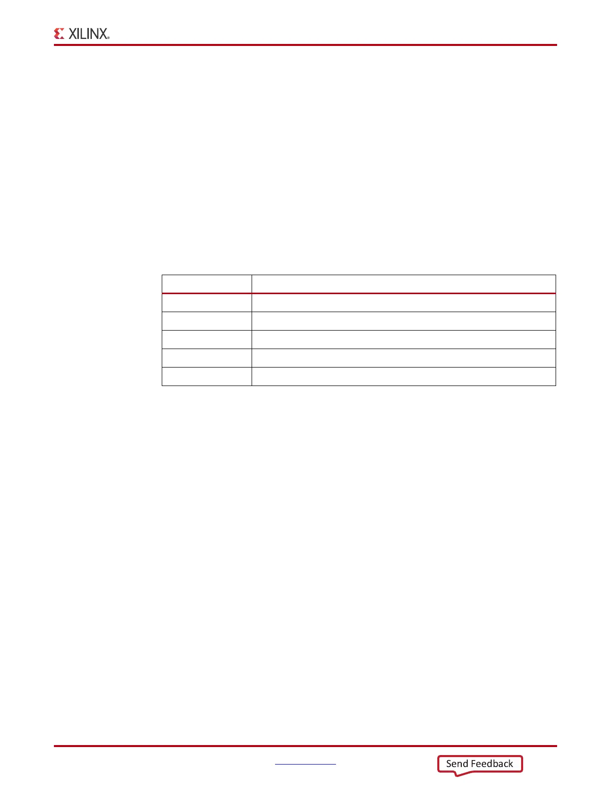
control register of the MUX as shown in Table 1-21.
Table 1-21: I
2
C Channel Assignments
U39 Channel I
2
C Component
0 SuperClock-2 module
1 7 series GTX transceiver power supply module
2FMC1
3FMC2
7FMC3
 Loading...

