8 www.xilinx.com VC7203 GTX Transceiver Characterization Board
UG957 (v1.3) October 17, 2014
Chapter 1: VC7203 Board Features and Operation
Power Management
Board 12V Input Power
The VC7203 board receives 12V main power through J2 (callout 3, Figure 1-2) using the
12V AC adapter that ships with the board. J2 is a 6-pin (2 x 3), right angle, Mini-Fit
connector.
Caution!
When supplying 12V through J2, use only the power supply provided for use with this
board (Xilinx part number 3800033).
Caution! Do NOT use a 6-pin, PC ATX power supply connector with J2. The pinout of the 6-pin, PC
ATX connector is not compatible J2 and the board will be damaged if an attempt is made to power it
from a PC ATX power supply connector.
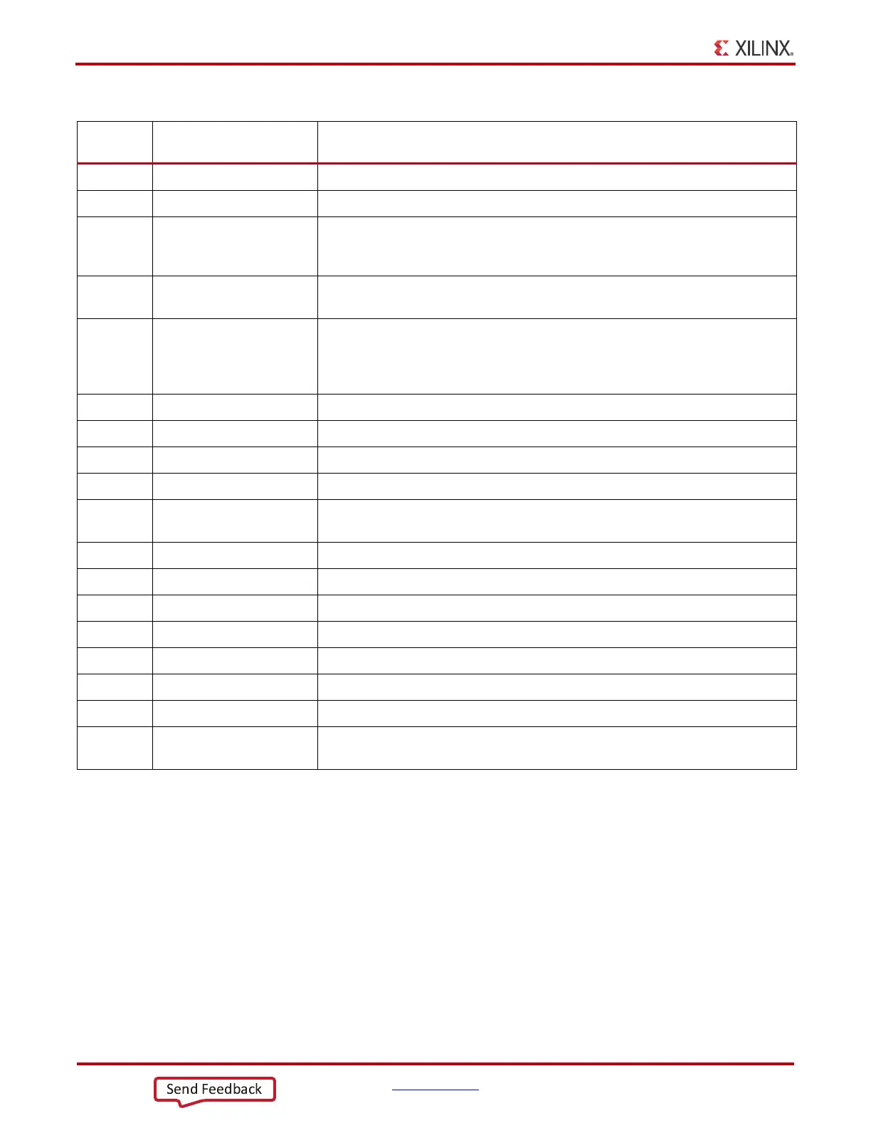
14 SW3 FPGA PROG_B pushbutton, page 17
15 DS11 12V power status LED, page 9
16
DS2, DS3, DS4, DS5, DS6,
DS8, DS9, DS10, DS26,
DS27, DS28, DS29
Status LEDS for FPGA logic, transceiver and utility power,
17
J199, J200, J201
J202, J203 J204
Power regulation jumpers for onboard regulators
18
J28, J29, J31, J32, J33,
J34, J35, J36, J37, J40,
J104, J105, J106, J107,
J177, J178, J196
External power supply jacks, page 12
19 GTX transceiver power supply module, page 13
20 J26 PMBUS connector, page 12
21 J79 Connector for USB to UART bridge (mini-B receptacle), page 29
22 J121 Power connector for active heatsink, page 13
23
DS13, DS14, DS15, DS16,
DS17, DS18, DS19, DS20
User LEDs (active-High), page 20
24 SW4, SW5 User pushbuttons (active-High), page 21
25 SW2 User DIP switches (active-High), page 20
26 J125 User I/O header, page 20
27 JA2 FMC1 connector, page 30
28 JA3 FMC2 connector page 30
29 JA4 FMC3 connector1 page 30
30 J98, J99, J100, J101 SMA connectors to differential MRCC pins on FPGA, page 18
31 J141, J142, R233
Jumpers and potentiometer for XADC reference and analog supply set-up,
page 44
Table 1-1: VC7203 Board Feature Descriptions (Cont’d)
Figure 1-2
Callout
Reference Designator Feature Description
 Loading...

