30 www.xilinx.com VC7203 GTX Transceiver Characterization Board
UG957 (v1.3) October 17, 2014
Chapter 1: VC7203 Board Features and Operation
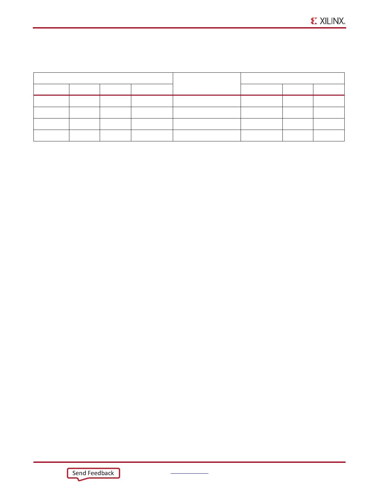
The bridge device also provides as many as 4 GPIO signals that can be defined by the user
for status and control information (Table 1-17).
A royalty-free software driver named Virtual COM Port (VCP) is available from Silicon
Laboratories. This driver permits the CP2103 USB-to-UART bridge to appear as a COM
port to the host computer communications application software (for example,
HyperTerminal or TeraTerm). The VCP driver must be installed on the host computer prior
to establishing communications with the VC7203 board.
FPGA Mezzanine Card HPC Interface
Callout 27, 28, and 29, Figure 1-2.
The VC7203 board features three high pin count (HPC) connectors as defined by the VITA
57.1 FPGA Mezzanine card (FMC) specification. The FMC HPC connector is a 10 x 40
position socket. See Appendix B, VITA 57.1 FMC Connector Pinouts for a cross-reference
of signal names to pin coordinates.
FMC1 HPC connector JA2 provides connectivity for:
• 68 differential user defined pairs:
• 34 LA pairs
• 17 HA pairs
• 17 HB pairs
•4 differential clocks
FMC2 HPC connector JA3 provides connectivity for:
• 68 differential user defined pairs:
• 34 LA pairs
• 17 HA pairs
• 17 HB pairs
•4 differential clocks
FMC3 HPC connector JA4 provides connectivity for:
• 65 differential user defined pairs:
• 34 LA pairs
• 16 HA pairs
• 15 HB pairs
•4 differential clocks
Table 1-17: CP2103 USB-to-UART Bridge User GPIO
FPGA (U1)
Schematic Net Name
Device (U34)
Pin Function Direction I/O Standard Pin Function Direction
B28 SelectIO In/Out LVCMOS18 USB_GPIO_0 19 GPIO In/Out
B29 SelectIO In/Out LVCMOS18 USB_GPIO_1 18 GPIO In/Out
A31 SelectIO In/Out LVCMOS18 USB_GPIO_2 17 GPIO In/Out
A32 SelectIO In/Out LVCMOS18 USB_GPIO_3 16 GPIO In/Out
 Loading...

