Do you have a question about the Xinuo XF-1069GF and is the answer not in the manual?
Introduces the product, covering appearance, packing list, installation, and getting started procedures.
Details the main page elements: ship position, cursor info, calendar, and satellite signal status.
Covers chart navigation: moving, zooming, backlight adjustment, display modes, and rotation.
Explains how to navigate and use the main menu for accessing various functions.
Manages tracks: switching, recording, setting parameters, and deletion.
Handles waypoints: adding, modifying, deleting, and calling for navigation.
Covers adding, modifying, and deleting markers on the chart.
Manages beacons: adding, modifying, deleting, and moving.
Guides on routes: adding, modifying, deleting, and calling for navigation.
Details accessory features like Tide data, viewing charts, and calendar.
Explains the Man Overboard (MOB) function for saving ship location.
Covers adding, operating, and managing draw lines on the chart.
Provides notes on waypoint and route navigation, including alarms.
Explains text input using Pinyin and English modes.
Covers system settings, alarms, display, and sound configurations.
Details signal check, versions, operate guide, and data exchange.
Displays recognized ships via AIS: MMSI, name, location, course, and speed.
Customizes AIS vessel display: ship size, hiding ships, and showing own ship.
Covers switching the Enhanced-A Mode for AIS functionality on or off.
Details receiving and displaying safety messages via AIS.
Manages AIS messages: outbox, inbox, new messages, and drafts.
Manages the address book for AIS communications.
Configures static AIS parameters like MMSI, category, name, and call sign.
Sets navigation-related parameters for the AIS system.
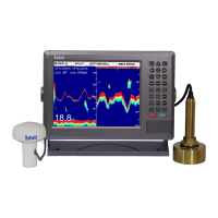
Overview of the fish finder's capabilities and basic functions.
Configures screen display: split modes, partition ratios for map and fish finder.
Sets the update speed for the fish finder image.
Adjusts screen space allocation between map and fish finder views.
Allows selection of different display scenes or modes for the fish finder.
Allows selection of different color palettes for the echo display.
Enhances fish visibility by reducing background noise.
Sets the unit of measurement for depth display (meter, FT, FM).
Controls the display of Variable Range Marker (VRM) for depth measurement.
Configures depth alarms for 'depth-water' or 'low-water' conditions.
Sets up alarms for detected fish based on size and color.
Adjusts signal amplification (gain) for optimal fish detection.
Sets the depth range for the sonar display, manually or automatically.
Controls the vertical shift of the sonar image for seabed tracking.
Reduces unwanted noise from phytoplankton and other echoes.
Highlights seabed contour with a white line for better fish echo identification.
Allows selection of background colors (Blue, Black, White) for the display.
Adjusts echo signal classification to improve display clarity.
Attenuates noise from phytoplankton and garbage echo reflections.
Automatically adjusts gain value to meet user requirements.
Displays echo in lateral deformation for estimating fish population size.
Sets sonic speed for depth measurements, affecting depth reading accuracy.
Sets correction value for water line to display depth from sea level.
Simulates echo patterns to demonstrate fish finder functions and adjustments.
Provides the overall appearance and physical dimensions of the unit in millimeters.
Illustrates the diagram for installing the unit, including components like gasket and knob.
Shows the diagram for counter mounting the unit, with dimensions in millimeters.
Presents the diagram for ceiling mounting the unit, with dimensions in millimeters.
Defines the external interfaces: POWER, NMEA, TD, and GPS ANT.
Details the definitions for the power interface, including polarity and voltage range.
Defines the pins for data interfaces, including GPS and AIS signal outputs.