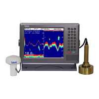
GPSChartPlotter&EchoSounder
46
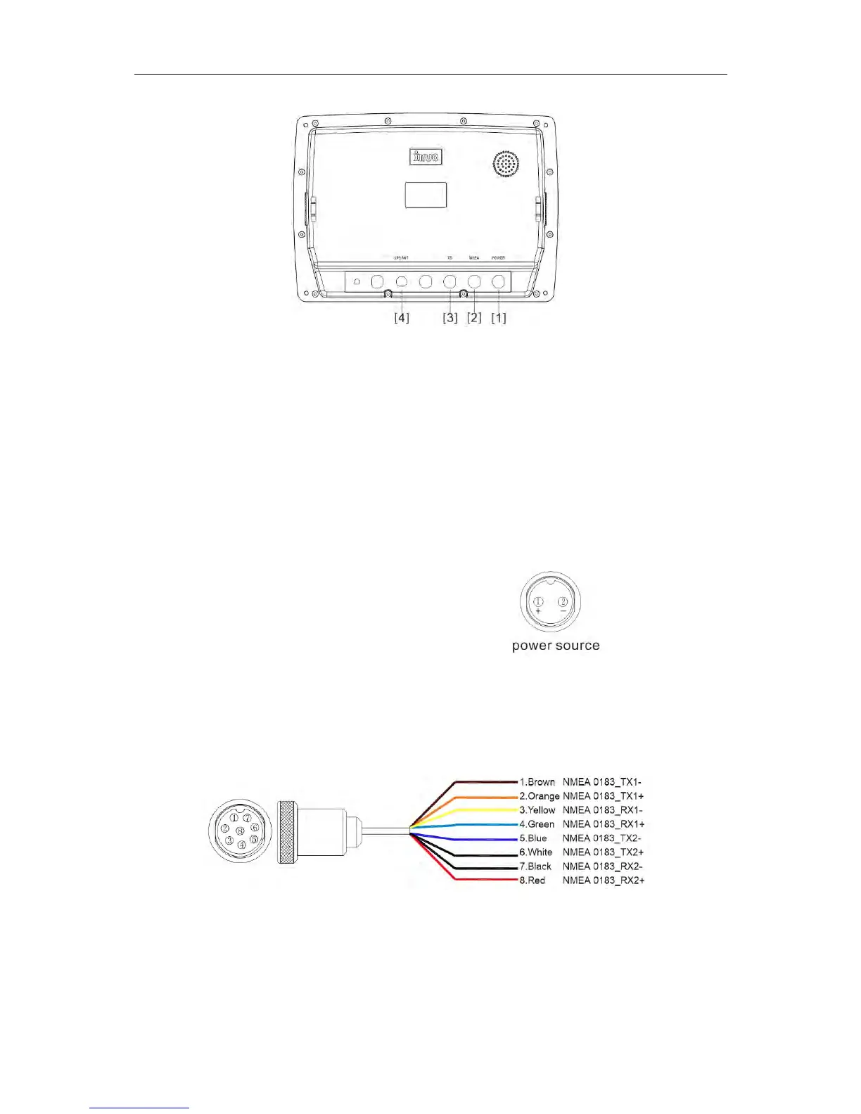
Appendix2:XF-1069GFWiringDiagram
Thedefinitionsofexternalinterfacesareshownasabove:
[1]POWER
[2]NMEA
[3]TD
[4]GPSANT
Powerconnectorisa2-pinsplug.Theredcableisforpositivepowersupplyinputwhilethe
black(orblue)cableisforthenegativepowersupplyinput.Connectthesetwocablesto24V
DCpowerofthevessel.Pleasepayattentiontothepolarity.(Pin1aspositiveandpin2as
negative.)
Thepowerinterfacedefinitionsareshownasright:
1---Thepositiveofthepower
2---Thenegativeofthepower
Note: ThevoltagerangeofpowersupplyinputisDC10V~36V.Donotexceedthisvoltage
range,orthedevicewillbedamaged.Andpleasemakesuretoconnecttheairoutlet
tightly.
Thedatainterfacedefinitionsareshownasbelow:
Note: thepinsof1,2aretheoutputofGPSsignal,thepinsof3,4,5,6aretheoutputofAIS
signal,thepinsof7,8aretheinputofHDT.