Page 14
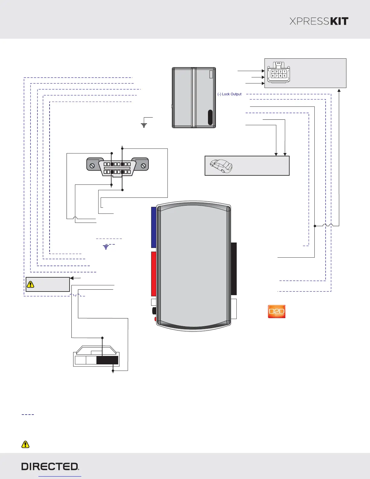
Installation Type 5
Remote
Starter
9: (+) Ignition InputPink:
10: (-) (Status) InputBlue/White: GWR
(+) 12V: 13Red:
(+) 12V
(-) Ground: 14Black:
See Reference
Chart for Door Lock
wire in vehicle.MUX
1: (-) Lock InputGreen:
2: (-) Unlock InputBlue:
[]1 ( ) Tach InpuAC t
(-) Door Status Input
[]2 (-) Hood Status Input
(+) Brake Status Input
TX: 10Yellow/Black:
[]2 (-) Hood Status Output: 12Blue/Red:
RX: 11Orange/Black:
( ) Door Lock Output: 9MUX Violet/Brown:
[]1 ( ) Tach Output: 5AC Violet/White:
(-) Door Status Output: 3Green/White:
(+) Brake Status Output: 6Gray:
(-) E-Brake Status Output: 1Black/White:
(-) E-Brake Status Input
P#: 2D65XKD
TX
(-) Ground
RX
(+)12V
10
RF
Prog Button.
LED
4
14
12
2
DBALL2
Diagnostic onnectorCOBDII
(connector side view)
18
169
HS CAN High: 3Tan/Black:
HS CAN Low: 4Tan:
HS CAN High: inP6
HS CAN Low: in 1P4
With the exception of the Diagnostic connector, all adapters are displayed from the wire side (unless specified otherwise).OBDII
MS CAN High: Orange/Green: 5
Ms CAN Low: Orange/Brown: 6
(-) (Status)GWR
(+) Ignition Output
(+) Accessory Output
(+) Starter Output
(-) Unl Outputock
(+) 12V Input
Ignition Connector
Refer to the Vehicle Wiring
Reference Chart for wire
and connector details.
( utput-) Trunk Release O [3]
(-) Parking Lights
Refer to the Vehicle Wiring
Reference Chart for wire
and connector details
(-) Ground
MS CAN High: inP3
MS CAN Low: in 1P1
4 123
Passive Anti-Theft
Security System (PATS)
connector
RX: Pin 1
TX: Pin 2
Not required in D2D mode.
[1] Tach wire is an optional connection required on some remote starters, which do not support a tach signal in D2D.
[2] Only if vehicle is equipped with OEM hood pin.
[]3 Trunk release output is ONLY required if trunk is not supported in data.
Rev.: 20170926
Platform: DBALL2
Firmware: MA2
© 2017 Directed. All rights reserved.