ADPROPROE by Xtralis Installation Guide
27386_05 19
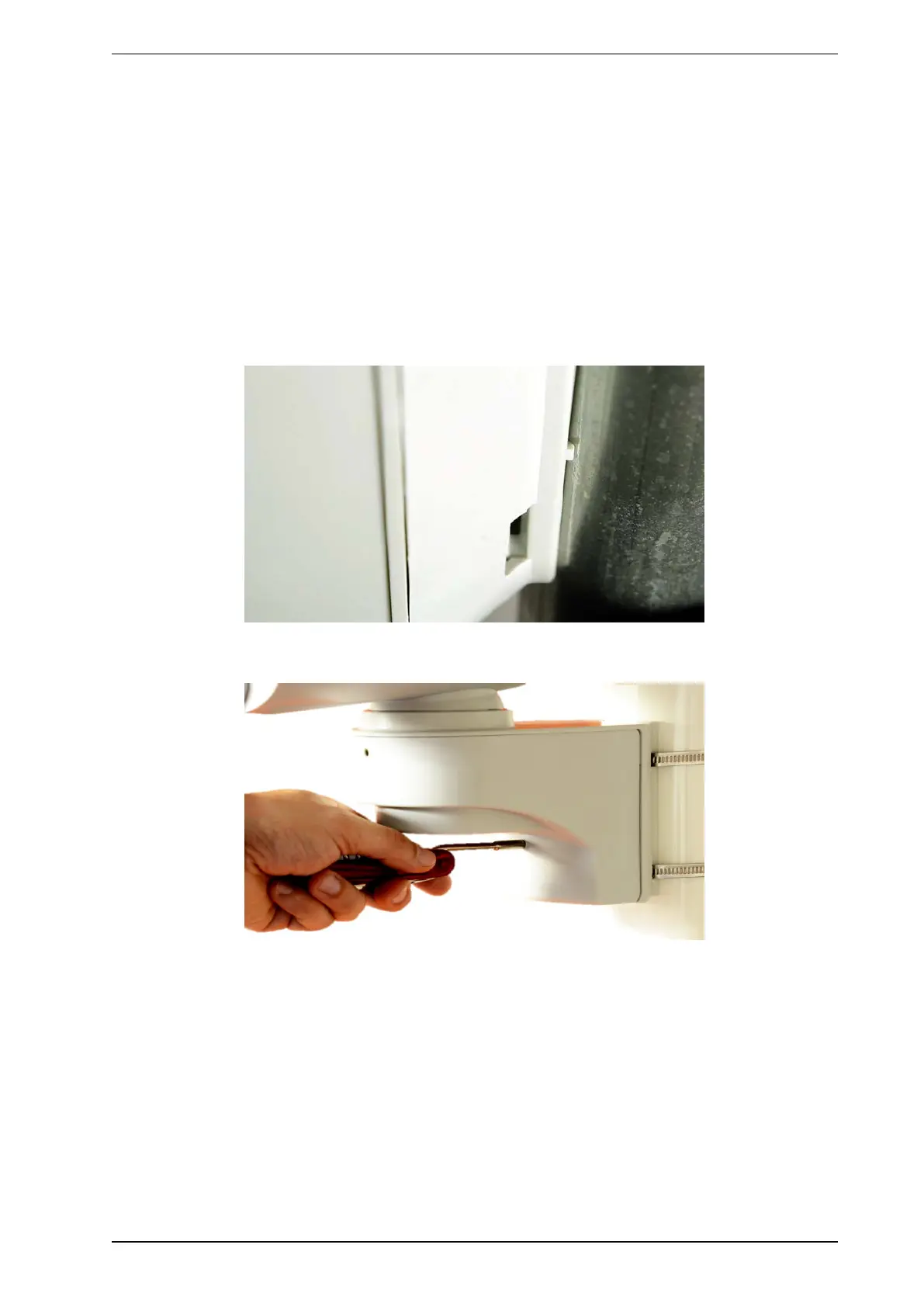
2.8.1 Fine adjustment of tamper switch
Note: If everything is correctly wired and no component of the tamper protection mechanism reports
tamper, the LED in the detector starts to blink for approximately one minute.
There are tamper switches both in the detector housing as well as in the cable routing. Before
configuring the rear tamper switch, therefore, make sure that the housing and cabling are correctly
closed as described above.
All ADPRO PROE-detector are equipped with a tamper switch in series, which detects any attempt to
remove the detector from its mounting point (pole or wall) in compliance with standards.
This switch must be configured such that even a minor loosening of a screw triggers a tamper alarm. The rear
tamper switch must therefore be mounted on the surface finish of the pole or wall if possible.
Configuring the rear tamper switch:
1. Check to see if the detector housing is properly closed.
2. Rotate the lower hexagon socket screw into the detector arm as shown until the tamper switch opens as
provided and the LED starts to blink.
3. Turn the screw another two or three rotations. The LED should continue to blink.