Xtreme Power Conversion Corporaon
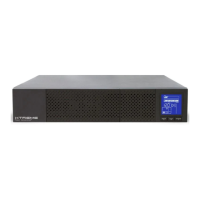
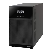
P91, TX91, TX91L, TXVR Service Manual
Page 26
Uninterrupble Power Supply
Regulaon Process for Single UPS
1. BUS voltage regulaon: When the UPS runs in AC mode, measure ±BUS voltage with the mulmeter, and
then regulate ±BUS voltages to 360±0.5V by using BUS regulaon command. (BUS voltage can be regulated
about 0.1V every point by using BUS regulaon command).
2. INV output voltage regulaon: When the UPS runs in the Inverter mode, measure the output voltage with
the mulmeter, and regulate the output voltage to 230±0.5V by using output voltage regulaon command.
(INV output voltage can be regulated about 0.1V every point by using output voltage regulaon command).
3. Output current regulaon: When the UPS runs in the Inverter mode with full R load, measure the output
current, and rread UPS sampled output current value by QGS command. Use OC command to regulate the
UPS sampled output current value to match your measured value. (Output current can be regulated about
0.1A every point by using output voltage regulaon command).
Notes:
1. Make sure the ground of the UPS connects to earth safely during parameter regulaon.
2. New assembly UPS must be regulated.
3. UPS which have been replaced CNTL and / or SPS-Charger board must be regulated again.
4. All the commands use capital leers.
5. All the above parameter regulaon cannot be accumulated.
6. All the regulaon will be saved in the ash memory of the CNTL when UPS shutdown with baery con-
nected.
7.2.6 Quick Start
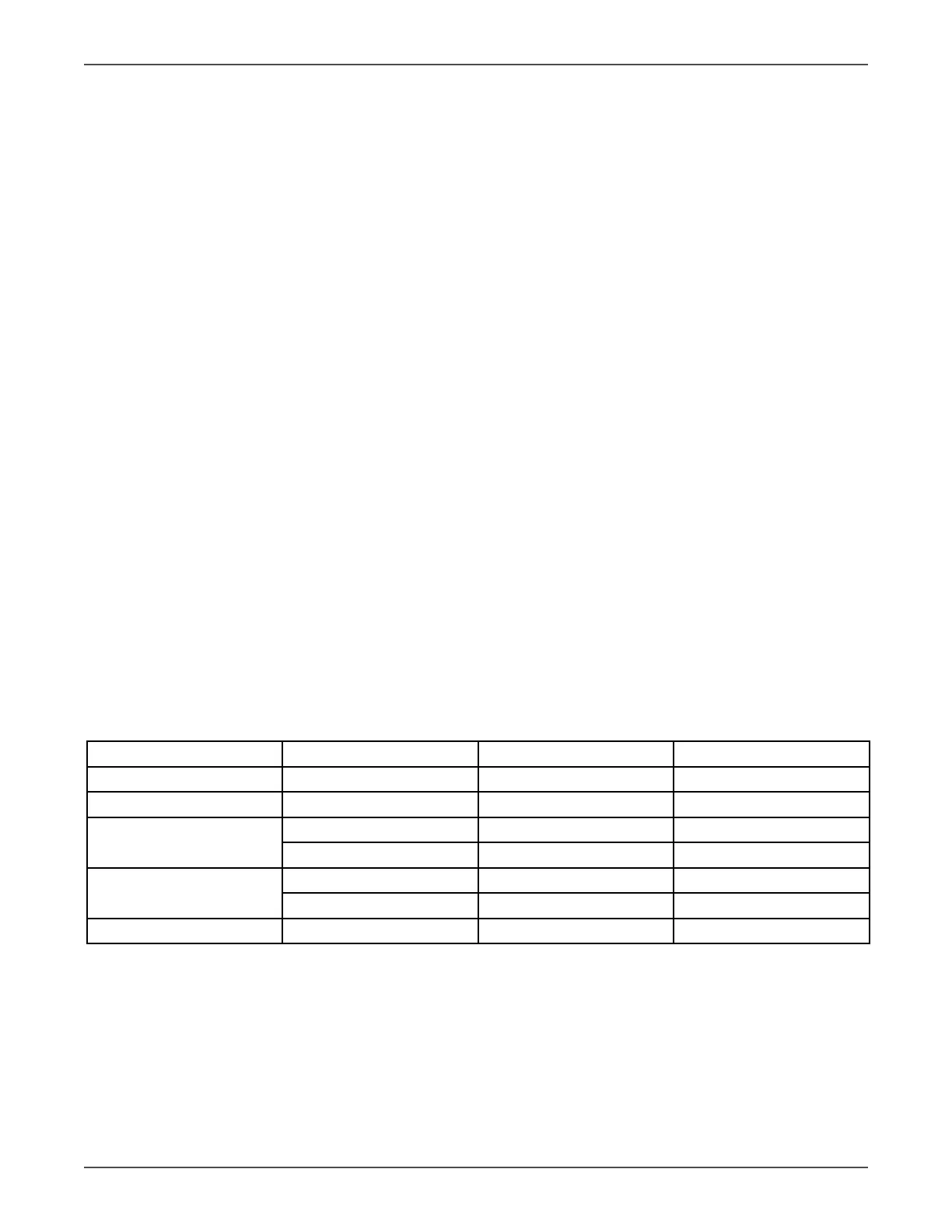
Before any detail check for UPS, please check the components listed in the following table. This acon could help
you nd problem quickly and make debug procedures go smoothly.
Note: Make sure that the capacitor voltage is lower than the safety voltage before disassembling any
parts to do checking procedure.
10k Main Power Secon
Circuit Block Checked components Component Type Failure condion
DC FUSE F3, F4 Fuse Open
Recer Q27, Q18, Q21 SCR A-K Short or open
PFC D33, D35 Diode Short or open
Q22, Q23, Q24, Q25 IGBT C-E short or open
INV D52, D62 Diode Short or open
Q7, Q8, Q9, Q10, Q12, Q15 IGBT C-E short or open
STS Q13, Q14, Q20, Q46 SCR A-K Short or open