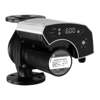
Parallel Offset
Angular Misalignment (degrees)
Figure 8: Acceptable parallel offset for TB Wood’s
®
Dura-Flex
®
elastomeric couplings
The following table relates the difference in measurement of the L1 and L2 dimensions
shown in Figure 6 of section 4.3.2 to the degree of angular misalignment between
coupling hubs.
Table 2: Allowable angular misalignment gap
Hub Size
1° angular
misalignment
2° angular
misalignment
3° angular
misalignment
4° angular
misalignment
in. (mm) in. (mm) in. (mm) in. (mm)
WE2 0.03 (0.8) 0.07 (1.7) 0.10 (2.5) 0.13 (3.3)
WE3 0.04 (1.0) 0.08 (2.1) 0.12 (3.1) 0.16 (4.1)
WE4 0.05 (1.1) 0.09 (2.3) 0.14 (3.5) 0.18 (4.6)
WE5 0.06 (1.4) 0.11 (2.8) 0.16 (4.2) 0.22 (5.5)
WE10 0.06 (1.6) 0.13 (3.2) 0.19 (4.9) 0.22 (5.5)
WE20 0.08 (2.0) 0.16 (4.0) 0.23 (5.9) N/A
WE30 0.10 (2.4) 0.19 (4.8) 0.28 (7.2) N/A
WE40 0.12 (2.9) 0.23 (5.9) 0.35 (8.8) N/A
WE50 0.14 (3.6) 0.28 (7.2) 0.43 (10.8) N/A
WE60 0.15 (3.9) 0.31 (7.7) N/A N/A
WE70 0.16 (4.1) 0.32 (8.2) N/A N/A
WE80 0.20 (5.0) 0.39 (10.0) N/A N/A
Falk
®
Steelflex
®
Couplings
Falk
®
Steelflex
®
T10 grid coupling alignment guidelines shown are also listed in the
coupling service manual published by Rexnord Falk
®
. Refer to the service manual for
more detailed information regarding coupling lubrication, fastener torque values,
detailed installation instructions, and more.
The following table shows both parallel and angular misalignment data as recommended
by the coupling manufacturer.
Table 3: Maximum parallel and angular misalignment offsets for Falk
®
Steelflex
®
T10 couplings
Hub Size
Parallel Offset Angular Offset
in. (mm) in. (mm)
1020T 0.006 (0.15) 0.003 (0.08)
1030T 0.006 (0.15) 0.003 (0.08)
1040T 0.006 (0.15) 0.003 (0.08)
1050T 0.008 (0.20) 0.004 (0.10)
4 Installation
e-XC INSTRUCTION MANUAL 25