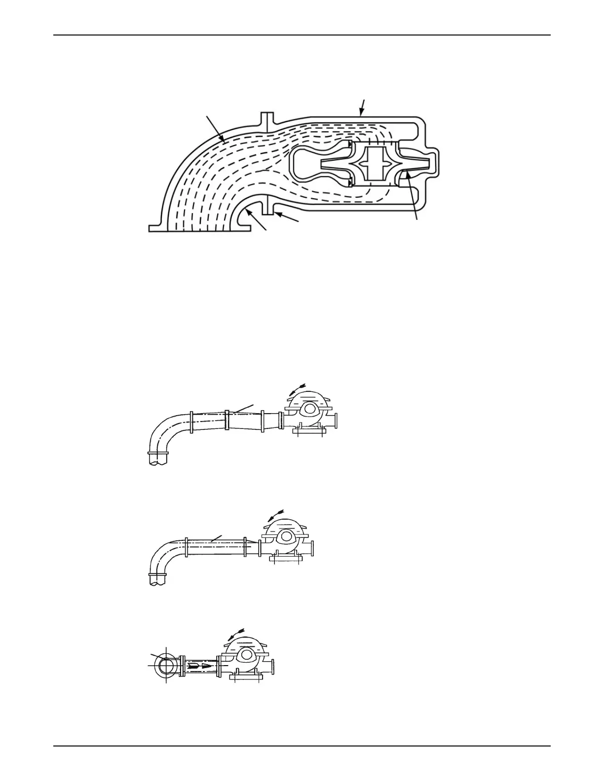
Example of unbalanced loading
This figure shows the unbalanced loading of a double-suction impeller due to the uneven
flow around an elbow that is adjacent to the pump:
1. Pump casing
2. Impeller
3. Pump suction flange
4. Suction elbow
5. Water velocity increases here and causes a greater flow to one side of the impeller.
Figure 10: Unbalanced loading of double-suction impeller
Examples
1. Level centerline of pipe
2. Check valve
3. Gate valve
4. Increaser
Figure 11: Suction pipe installed with a gradual rise to the pump – correct
1. Air pocket
Figure 12: Suction pipe installed with a gradual rise to the pump – incorrect
1. Air pocket
Figure 13: Suction pipe installed with a reducer – incorrect
1. Air pocket
Figure 14: Incorrect
4 Installation
e-XC INSTRUCTION MANUAL 29