1. Unfasten the top two hex bolts [6] that secure the two mounting brackets [5] to the top
half of the inner coupling guard assembly [1].
2. Unfasten the two hex bolts [6] located on the top two faces of the outer hex guard
assembly [2].
3. Remove the clips [3] and two square spacers [4] which secure the upper and lower
halves of the outer [2] and inner [1] guard assemblies by unfastening the four hex head
bolts [6] that are threaded into each clip [4]. Remove the upper halves of the guard
assemblies by lifting upwards.
Note: The coupling should now be exposed and the lower guard assembly should still
be attached to the mounting bracket [5]. Coupling maintenance may be performed
without further disassembly of the guard.
4. Uncouple the lower halves of the outer [2] and inner [1] guard assemblies by removing
the two hex head bolts [6] located on the bottom two faces of the hex guard assembly.
5. Detach the bottom half of the inner guard [1] from the mounting bracket [5] by
unfastening the two hex bolts [6] located on the bottom half of the mounting bracket.
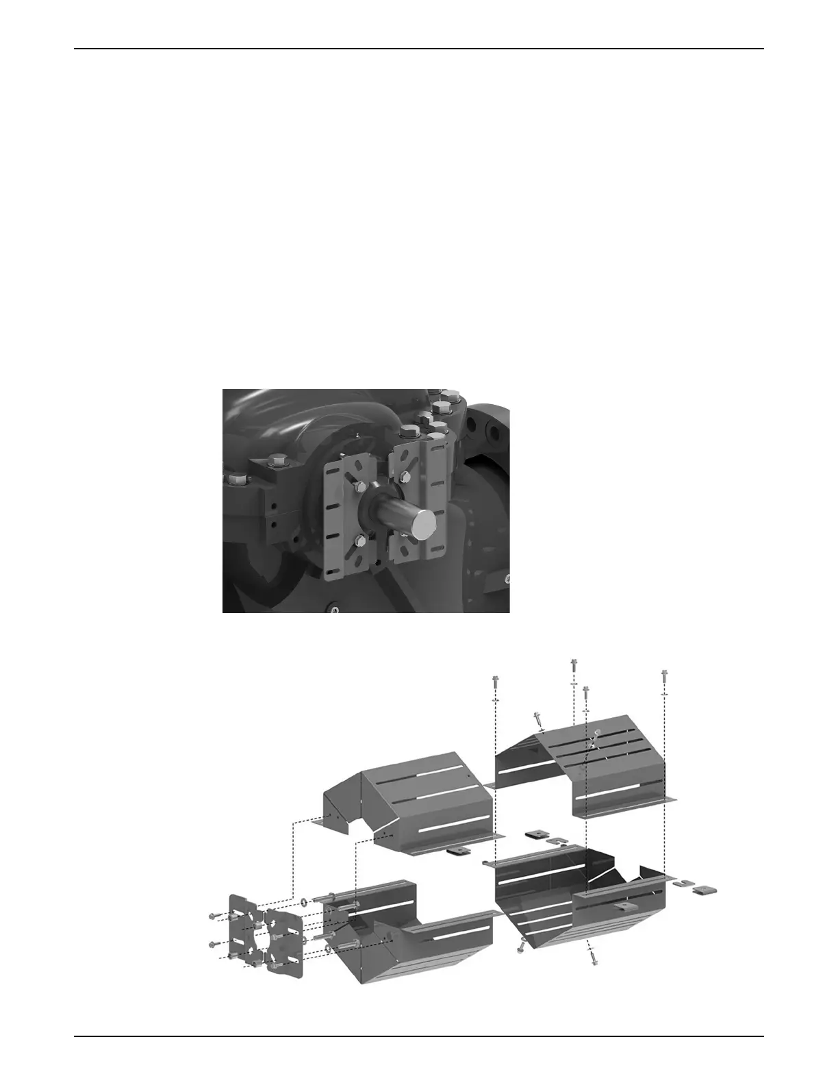
6. If desired, the mounting bracket [5] may be removed from the inboard bearing gland
of the pump by removing the four bearing gland bolts [8] which secure the brackets in
place.
Figure 31: Large bracket mounted to pump bearing gland (without guard assembly)
Figure 32: Coupling guard disassembly diagram
6 Maintenance
e-XC INSTRUCTION MANUAL 49