15. • EU: Gray
• US: Red
16. Screen lead of the shared communication cable
17. Signal leads of the shared communication cable
18. Pump 2
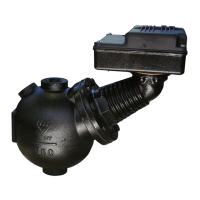
19. Level sensor
20. Screen lead of the level sensor cable
21. Level sensor lead –
22. Level sensor lead +
23. White, not connected
24. Pump 3
Table 3: Power
Terminal Type Function
1 L1/L Incoming power to the drive
2 L2/N Incoming power to the drive
3 L3 Incoming power to the drive
4 U Outgoing power for the pump
5 V Outgoing power for the pump
6 W Outgoing power for the pump
Table 4: Control I/O
Terminal Type Function
1 +24 V output (maximum 100 mA) +24 V external supply for backup power
2 Digital input 8–30 V DC Pump block input
3 Digital input 8–30 V DC External alarm reset
4 Digital input 8–30 V DC Level switch
5 +10 V output (maximum 20 mA Out) Unused
6 Analog input 0–20 mA Pump sensor (T2)
7 Ground (earth)
8 Analog output 4–20 mA Level sensor output
9 Ground (earth)
10 Analog input 4–20 mA Level sensor input
11 Digital output 0–10 V Pump running output
12 Hardware inhibit input
13 Hardware inhibit output (0 V)
Relay
14 Relay 1 common, 250 V AC, 30 V DC, 5 A User configurable relay #1 (A-sum alarm)
15 Relay 1 NO, 250 V AC, 30 V DC, 5 A User configurable relay #1 (A-sum alarm)
16 Relay 1 NC, 250 V AC, 30 V DC, 5 A User configurable relay #1 (A-sum alarm)
17 Relay 2 common, 250 V AC, 30 V DC, 5 A User configurable relay #2 (Pump running output)
18 Relay 2 NO, 250 V AC, 30 V DC, 5 A User configurable relay #2 (Pump running output)
Table 5: Extension relay card
Terminal Type Function
1 Relay 3 common, 250 V AC, 30 V DC, 5 A User configurable relay #3
Electrical Installation
SRC 311 - SmartRun
™
Installation, Operation, and Maintenance Manual 27