• Ensure that the minimum mounting clearance is observed according to Mounting
clearance (page 15).
• Ensure that sufficient cooling is provided.
1. Drill four holes in the supporting wall.
See Dimensions (page 13).
Do not carry out drilling operations with the drive in place. Dust and swarf from
drilling may lead to damage.
2. Mount the drive and tighten the screws.
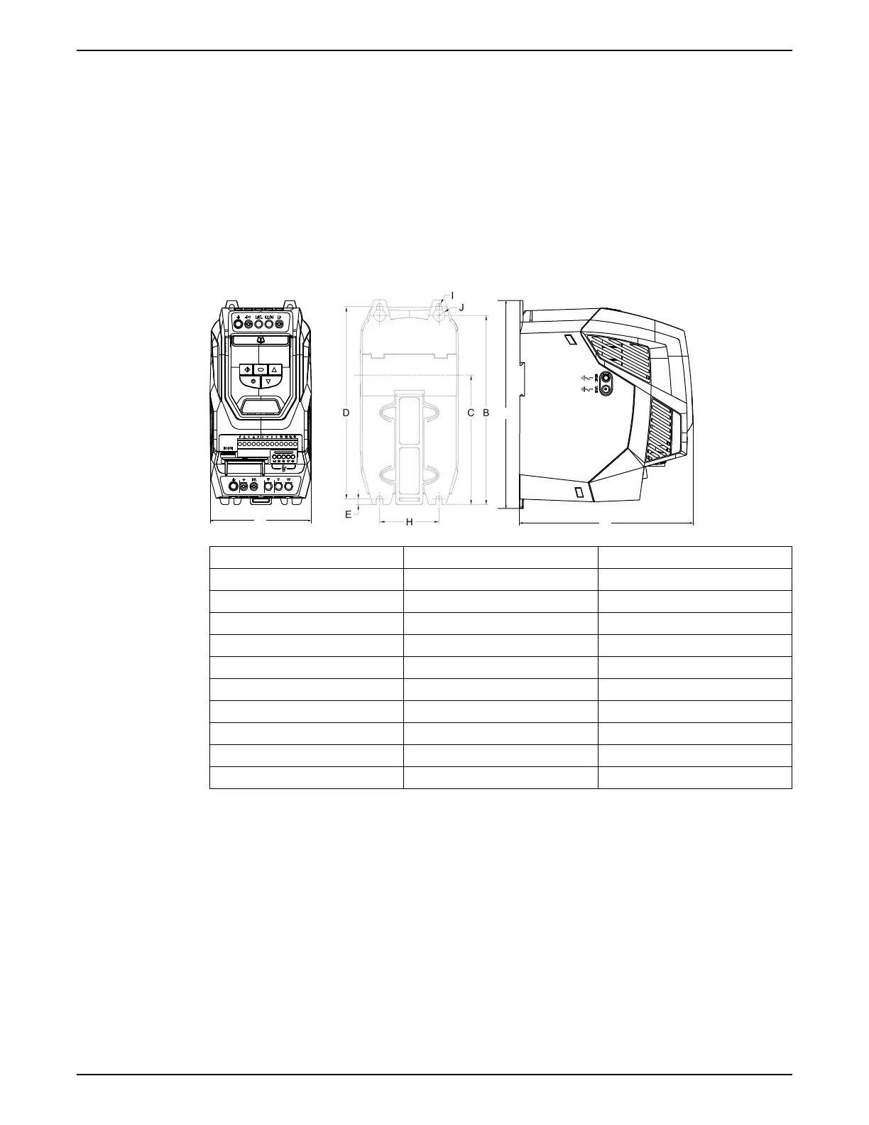
Dimensions
IP20
Frame size 2 3
A mm (in) 221 (8.70) 261 (10.28)
B mm (in) 207 (8.15) 246 (9.69)
C mm (in) 137 (5.39) - (-)
D mm (in) 209 (8.23) 247 (9.72)
E mm (in) 5.3 (0.21) 6 (0.24)
F mm (in) 185 (7.28) 205 (8.07)
G mm (in) 112 (4.41) 131 (5.16)
H mm (in) 63 (2.48) 80 (3.15)
I mm (in) 5.5 (0.22) 5.5 (0.22)
J mm (in) 10 (0.39) 11 (0.39)
Mechanical Installation
SRC 311 - SmartRun
™
Installation, Operation, and Maintenance Manual 13