en - Original instructions
20 e-SV series - Installation, Operation and Maintenance Manual
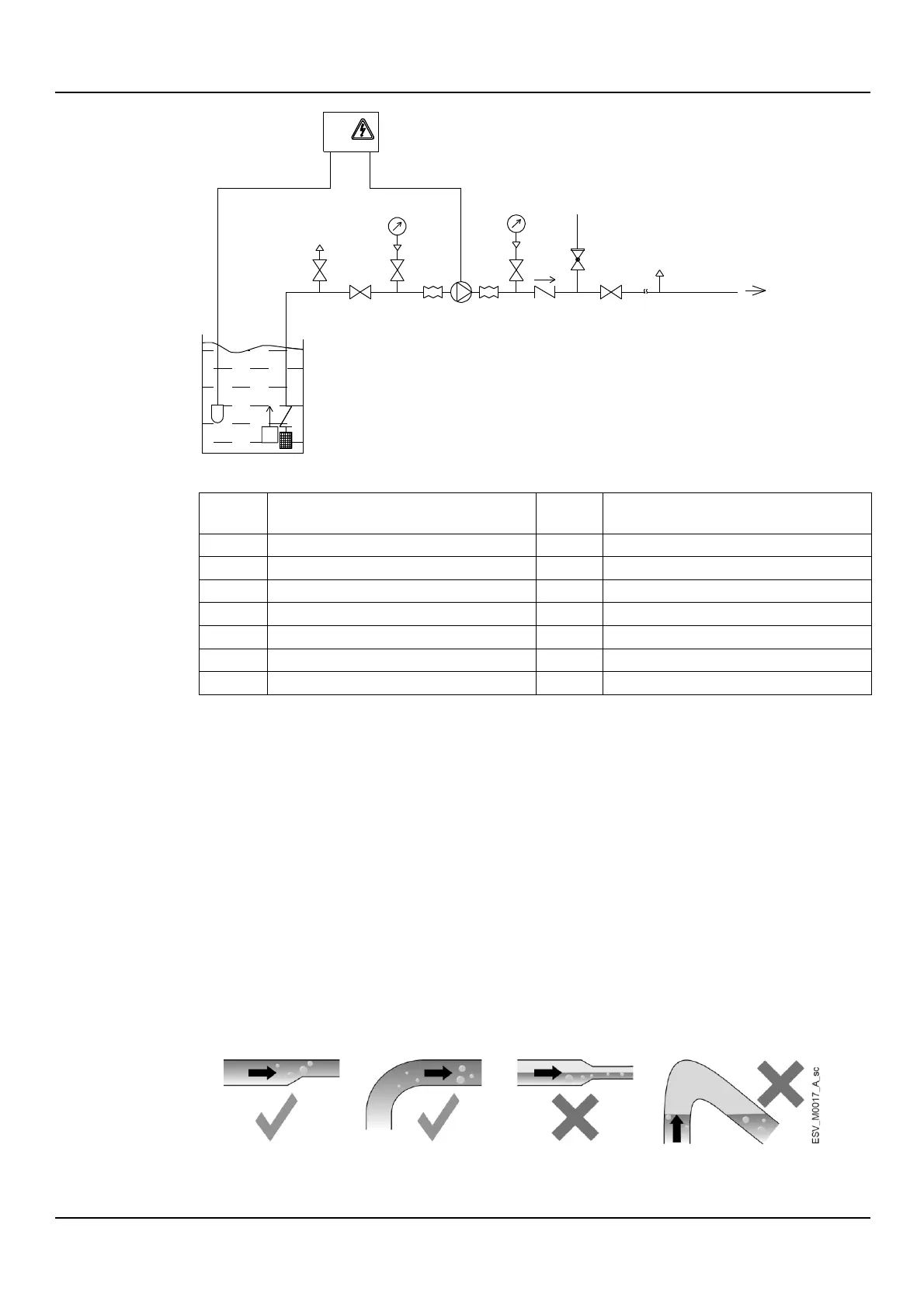
Figure 12: Suction lift installation diagram
Electrode probes or float
Overpressure safety on-off valve
Foot check valve with filter
1. Do not install the unit at the lowest point of the system, to avoid the accumulation of
sediments.
2. Install an automatic relief valve at the highest point of the system to eliminate air bubbles.
3. Remove any welding residues, deposits and impurities in the pipes that could damage the
unit; install a filter if necessary.
4. Support the pipes independently to prevent them from weighing on the unit.
5. To reduce the transmission of vibrations between the unit and the system and vice versa,
install:
anti-vibration joints on the suction and discharge sides of the unit
dampers between the unit and the surface on which it is installed.
6. In order to reduce flow resistance, the pipe on the suction side must be:
As short and as straight as possible
For the section connected to the unit, straight and without bottlenecks, covering a
length equal to at least six times the diameter of the suction port
Wider than the suction port; if necessary, install an eccentric reducer that is horizontal
on top
Without bends; if this cannot be avoided, bends of a radius as wide as possible
Without traps and 'goosenecks'
With on-off valves with a low specific flow resistance.
7. Install a check valve on the discharge side to prevent the liquid from flowing back into the
pump unit when this is at standstill.
EHM_M0017_A_sc
7
11
5
4
4 2 2
5
4
8
10
3
Q
4
9
1
13
 Loading...