en - Original instructions
e-SV series - Installation, Operation and Maintenance Manual 19
Table 1: Sizes of the anchoring bolts
1. If present, remove the plugs covering the suction and discharge ports.
2. Place the unit on a level and sturdy surface.
3. Using a spirit level, make sure that the unit is level.
4. Align the suction and discharge ports to their piping.
5. Secure the unit using 4 bolts with resistance class 8.8 or higher; see the table.
Also see the Vibration reduction and the Hydraulic connection sections.
4.2.5 Reducing vibrations
The motor and the flow of liquids in the pipes may cause vibrations, which can be exacerbated
by incorrect installation of the unit and pipes. See the Hydraulic connection section.
4.3 Hydraulic connection
DANGER:
All the hydraulic and electrical connections must be completed by a technician possessing the
technical-professional requirements outlined in the current regulations.
WARNING:
Piping must be sized to ensure safety at the maximum operating pressure.
WARNING:
Install appropriate seals between the unit couplings and the pipings.
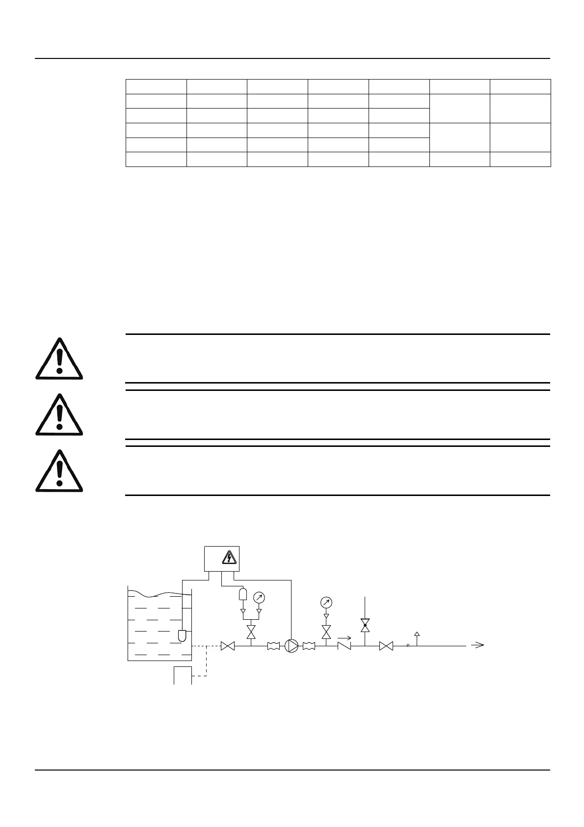
4.3.1 Guidelines for the hydraulic system
Refer to the representative hydraulic diagrams; see the figures below.
Figure 11: Positive suction head installation diagram
EHM_M0016_A_sc
11
5
5
6
8
74 2 2 4
4
4
9
3
Q
1
12

 Loading...