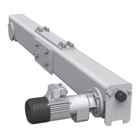
4.3.3 Drive shaft for trolley drive (trolley KE-S76)
The drive shaft is suitable for girder flange widths “B” from 4.9 in. to 19.7 in.
1. Insert drive shaft (5) into the two drive pinions (6) from the counterweight side, then
assemble spacer tube (7) and adjusting ring (8).
2. Adjust drive shaft (5) so that on the hoist side the shaft end projects by between
min. 0 in. and max. 4.72 in. beyond the drive pinion (6) and on the counterweight
side the shaft end projects by between min. 1.9 in. and max. 6.3 in. beyond the
trolley side cheek (10).
3. Lock adjusting ring (8) with adjusting screw so that on spacer tube (7) lying against
drive pinion (6) there is a play of approx. 0.079 - 0.157 in. to adjusting ring (8).
4. After fitting travel drive, check drive shaft (5) for ease of movement.