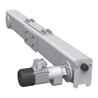
Adjust hoist limit switch at the setscrews (S1) - (S6) depending on version:
Turning to the left: switching point is moved “downwards”.
Turning to the right: switching point is moved “upwards”.
Adjusting en bloc
All the cam discs can be moved together with the aid of the black setscrew (S0). The
settings of the individual contacts relative to one another remain unchanged (see Fig.
80).
Set the limit switch using socket spanner (04 430 50 99 0) and without using undue
force. Do not use a power screwdriver.
Adjust the switching points in the following sequence:
1. A↑ (S1)
2. B↑ (S3)
3. B↑↑ (S4)
4. A↓ (S2)
5. B↓ (S5) (option)
6. B↓↓ (S6) (option)
When setting the hoist limit switch, observe hook dimension “C” as specified on page 76,
section 7.11 “Hook dimensions C for KE-S.. trolleys”.
Switching point A↑ (S1)
Emergency hoist limit switch top hook position
1. Set without load in creep lifting.
2. Lift bottom hook block to a+0.39 in. (see illustration left and table below) or the hook
dimension C-2 in. see Tab. 37, page 76, depending on which dimension is greater If
necessary turn setscrew (S1) to the right beforehand.
3. Turn setscrew (S1) to the left until contact S1 switches audibly.
4. Activate override button (S261) in control panel and at the same time “down” button
to leave the hoist limit switch area.
5. Check cut-off point at fast and slow speed.