Centering connection piece
1. Loosen nuts (5) and shift connection piece (6) on connecting bolt (7) so that
dimensions “z1” and “z2” between trolley side cheeks (4) and connection piece (6)
are equal on both sides.
2. Tighten nuts (5) with a torque spanner to the specified tightening torque (see table
above).
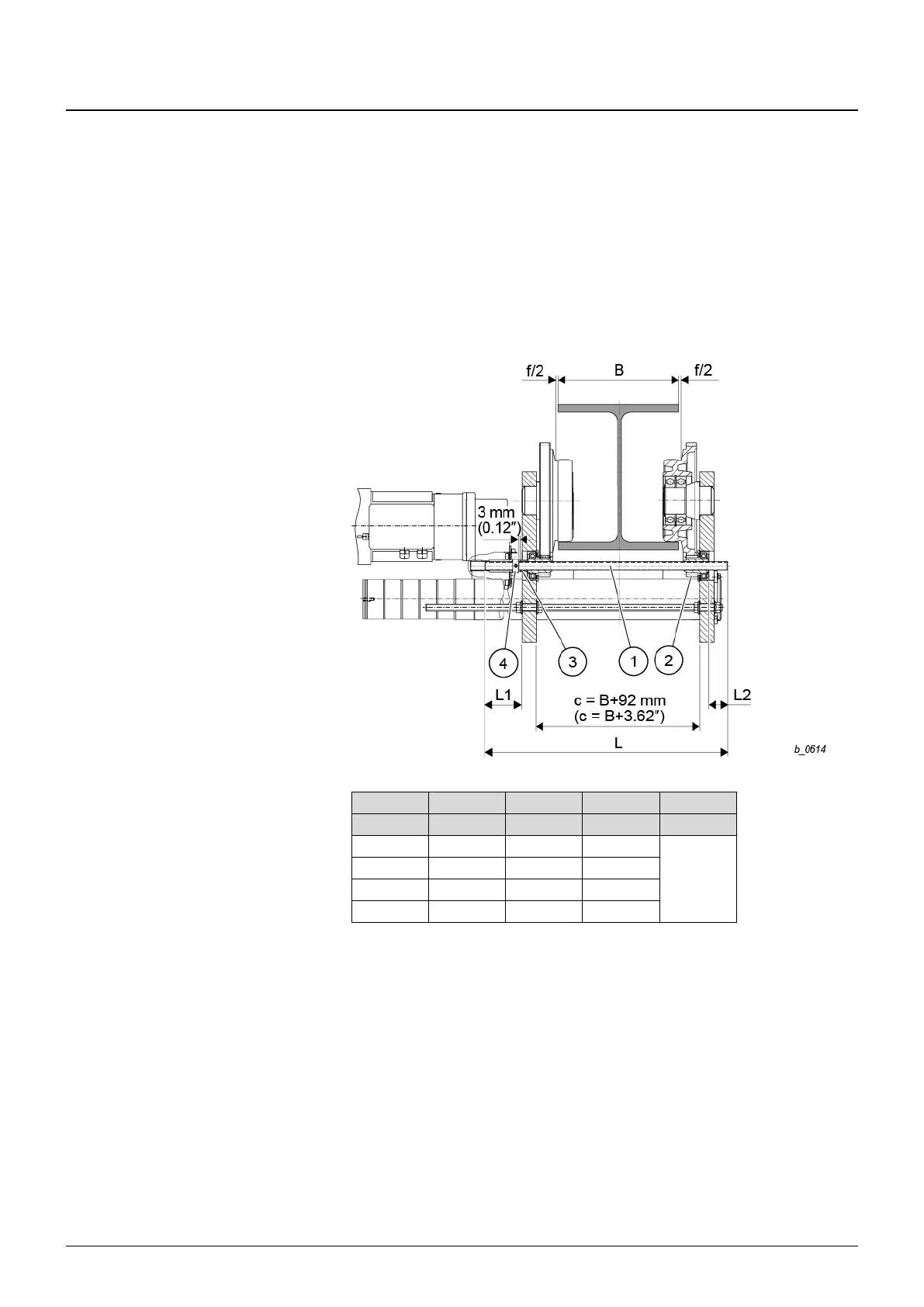
Connecting bolt and drive shaft
3. Use connecting bolt and drive shaft suitable for beam range “B” (for dimensions, see
Fig. 19).
Drive shaft for trolley drive (trolley UE-S776)
Tab. 12
The drive shaft is suitable for girder flange widths “B” from 7.3 in. to 19.7 in. (see Tab.
12 for length “L”).
1. Insert drive shaft (1) into the two drive pinions (6) from the counterweight side, then
assemble spacer tube (3) and adjusting ring (4).
2. Adjust drive shaft (1) to dimension “L1”, dimension “L2” must lie between the values
given in the table.
3. Lock adjusting ring (4) with adjusting screw.
4. After fitting travel drive, check drive shaft (1) for ease of movement. The axial play
must be approx. 2 – 4 mm (0.08 – 1.57 in.)