CL Editor Owner’s Manual
30
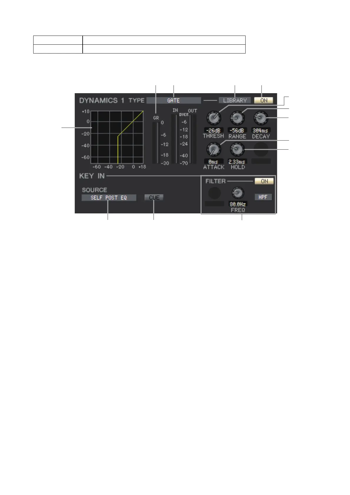
❏ DYNAMICS1/2
You can select one of the following types for each of the two dynamics processors.
If GATE/DUCKING is selected
1 TYPE
Indicates the type of the currently selected gate/ducking. You can click here to select the type. Ducking is the effect that
activates compressor triggered by another sound source.
2 LIBRARY
This button accesses the dynamics library. Clicking this button will open the DYNAMICS page of the Library window.
3 ON
This button switches on/off for the gate or the ducking.
4 Response curve
Indicates the response for the gate/ducking of the currently selected channel.
5 GR meter (Gain Reduction meter)
This meter indicates the amount of gain reduction produced by the gate/ducking.
6 THRESH (Threshold level)
Specifies the level (the threshold level) at which the gate/ducking will activate. The gate will open (or the ducking will
activate) when the key-in signal exceeds this level, and the gate will close (or the ducking will deactivate) when the sig-
nal falls below this level.
7 RANGE
Specifies the amount by which the signal is attenuated while the gate is closed (or while the ducking is activated.)
8 DECAY
Specifies the time over which the gate will close (or the time to return to normal signal gain of ducking) after the hold
time has elapsed.
9 ATTACK
Specifies the time from when the key-in signal exceeds the threshold level until the gate opens (or from when the duck-
ing has been triggered until the signal is ducked.)
0 HOLD
Specifies the time that the gate will remain open (or the ducking will remain activate) after the key-in signal falls below
the threshold.
DYNAMICS1 GATE, DUCKING, COMPRESSOR, EXPANDER
DYNAMICS2 COMPRESSOR, COMPANDER-H, COMPANDER-S, DE-ESSER
 Loading...