32 Chapter 2—Control Surface & Rear Panel
DM2000—Owner’s Manual
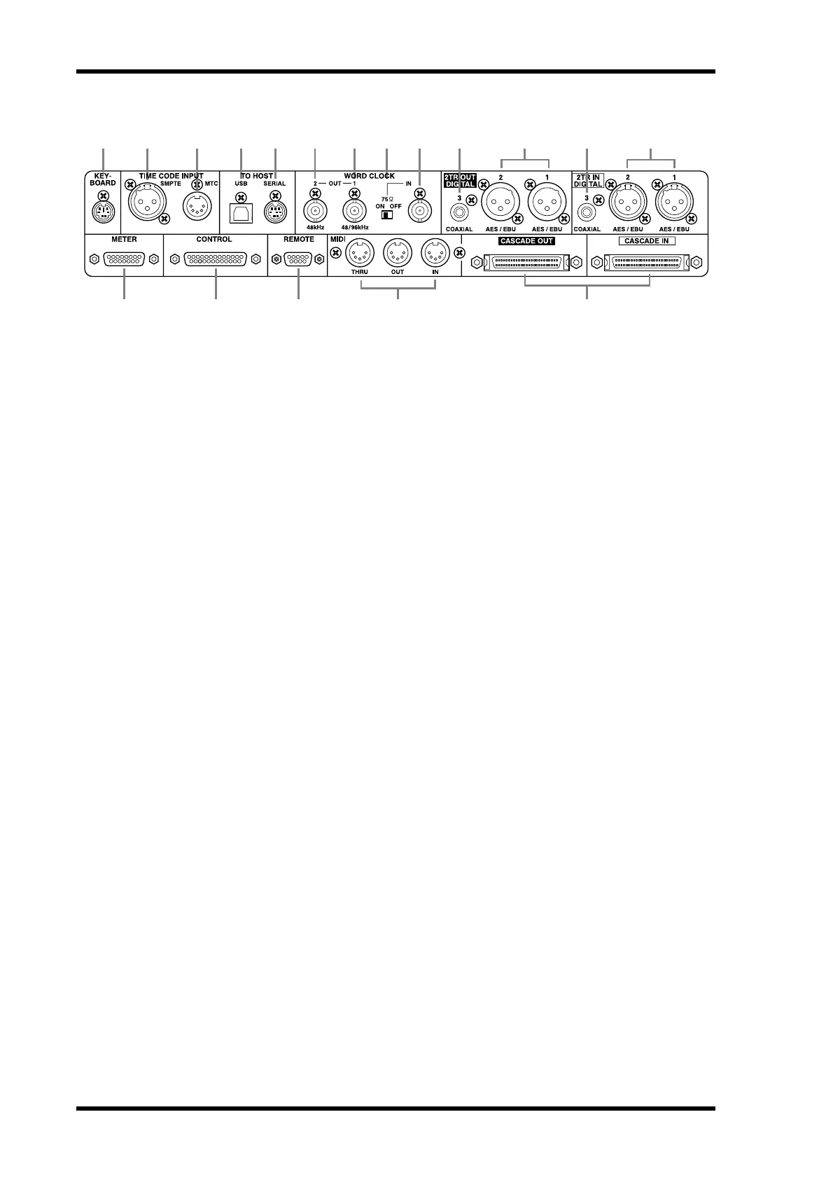
Digital I/O & Control Section
A KEYBOARD connector
A PS/2 compatible keyboard can be connected here for quick entry of scene and library
titles and channel names. See “Using a Keyboard” on page 38 for more information.
B SMPTE TIME CODE INPUT connector
This balanced XLR-3-31-type connector is used to input SMPTE timecode for synchroniz-
ing the Automix function. See “Selecting the Timecode Source & Frame Rate” on page 171.
C MTC TIME CODE INPUT connector
This 5-pin DIN connector is used to input MTC for synchronizing the Automix function.
See “Selecting the Timecode Source & Frame Rate” on page 171.
D USB TO HOST port
This USB port is for MIDI communication between the DM2000 and a host computer with
a USB port. See “MIDI I/O” on page 182 for more information.
E SERIAL TO HOST port
This 8-pin mini DIN port is for MIDI communication between the DM2000 and a host
computer with a serial port. See “MIDI I/O” on page 182 for more information.
F WORD CLOCK OUT 2 connector
This BNC connector outputs a wordclock signal at half the clock rate of the DM2000 when
using 88.2 kHz or 96 kHz. See “Wordclock Connections” on page 50 for more information.
G WORD CLOCK OUT 1 connector
This BNC connector outputs a wordclock signal at the same clock rate as the DM2000. See
“Wordclock Connections” on page 50 for more information.
H WORD CLOCK 75Ω ON/OFF termination switch
This switch applies 75Ω termination to the WORD CLOCK IN. See “Terminating External
Wordclocks” on page 52 for more information.
I WORD CLOCK IN connector
This BNC connector is for connecting an external wordclock signal. See “Selecting the
Wordclock Source” on page 51 for more information.
J 2TR OUT DIGITAL COAXIAL 3
This phono connector outputs consumer format (IEC-60958) digital audio, and is typically
connected to the digital stereo input of a 2-track recorder. The following signals can be
patched to this output: Stereo Out, Bus Outs, Aux Sends, Matrix Sends, Direct Outs, Insert
Outs, and Control Room. The sampling rate of the digital audio output can be set indepen-
dently of the DM2000 sampling rate by using the internal sampling rate converter. Dither
can be applied for digital audio transfer to lower-resolution systems. See “2TR Digital Outs”
on page 52 for more information.
1 2 3 4 5 6 7 8 9J KL
N O P RQ
M
 Loading...