27
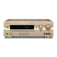
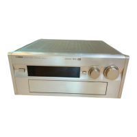
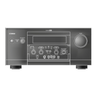
DSP-A595a
IC4 : YSS918D-F (AC3D2av)
DSP + AC-3 (Digital Dolby)/Pro Logic/DTS Digital Surround Decoder
No. Name I/O Function
1 VDD1 +5V power supply
2 RAMCEN O RAM chip enable output terminal (normally unconnected)
3 RAMA16 O RAM address output terminal 16, connected to external 1M SRAM address
4 RAMA15 O RAM address output terminal 15, connected to external 1M SRAM address
5 SDIB0 I Serial data input B terminal 0 (normally connected to ground)
6 SDIB1 I Serial data input B terminal 1 (normally connected to ground)
7 SDIB2 I Serial data input B terminal 2 (normally connected to ground)
8 XI I
I
Crystal oscillator connection external clock input terminal
9 XO O Crystal oscillator connection (normally unconnected)
10 VSS Ground
11 AVDD +3V power supply
12 SDIB3 Serial data input B terminal 3 (normally unconnected)
13 TEST Test terminal (normally unconnected)
14 TEST Test terminal (normally unconnected)
15 OVFB O
O
O
O
Overflow detect terminal (normally unconnected)
16 DTSDATA DTS data detect terminal (normally unconnected)
17 AC3DATA AC-3 data detect terminal (normally unconnected)
18 SDOB3 Serial data output B terminal 3 (normally unconnected)
19 CPO O PLL output terminal (connected to AVSS through external analog filter)
20 AVSS Ground
21 VDD +3V power supply
22 SDOA2 O Serial data output A terminal 2 (normally unconnected)
23 SDOA1 O Serial data output A terminal 1 (normally unconnected)
24 SDOA0 O Serial data output A terminal 0, PCM output terminal (AC-3/PRO LOGIC/DTS: L/R output)
25 RAMA14 O RAM address terminal 14 output terminal, connected to external 1M SRAM address
26 RAMA13 O RAM address terminal 13 output terminal, connected to external 1M SRAM address
27 RAMA12 O RAM address terminal 12 output terminal, connected to external 1M SRAM address
28 RAMA11 O RAM address terminal 11 output terminal, connected to external 1M SRAM address
29 RAMA10 O RAM address terminal 10 output terminal, connected to external 1M SRAM address
30 VSS Ground
31 VDD1 +5V power supply
32 OPORT0 O Output port terminal 0, dolby pro logic signal output
33 OPORT1 O Output port terminal 1, (normally unconnected)
34 OPORT2 O Output port terminal 2, (normally unconnected)
35 OPORT3 O Output port terminal 3, (normally unconnected)
36 OPORT4 O Output port terminal 4, (normally unconnected)
37 OPORT5 O Output port terminal 5, (normally unconnected)
38 OPORT6 O Output port terminal 6, (normally unconnected)
39 OPORT7 O Output port terminal 7, (normally unconnected)
40 VSS Ground
41 VDD2 +3V power supply
42 RAMA9 O RAM address output terminal 9 , connected to external 1M SRAM address
43 RAMA8 O RAM address output terminal 8 , connected to external 1M SRAM address
44 RAMA7 O RAM address output terminal 7 , connected to external 1M SRAM address
45 SDOB2 O Serial data output B terminal 2, PCM output
46 SDOB1 O Serial data output B terminal 1, PCM output
47 SDOB0 O Serial data output B terminal 0, PCM output
48 SDBCK1 I Serial data bit clock input terminal 1
49 SDWCK1 I Serial data word clock input terminal 1
50 VSS Ground


 To Next Page