RX-V1800/HTR-6190/DSP-AX1800
14
345 8 0
D
E
G
F
H
C
B
J
K M NL O P
R Q
I
1
2
3
4
5
6
7
8
9
0
A
B
C
D
E
F
G
H
I
J
K
L
M
N
O
P
Q
R
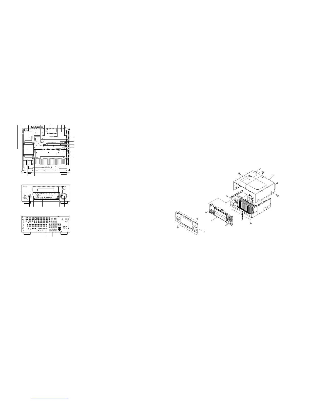
Power Transformer
POWER (4) P.C.B.
POWER (2) P.C.B. (R, L models)
TUNER
MAIN (2) P.C.B.
FL (3) P.C.B.
FL (5) P.C.B.
FL (6) P.C.B.
FL (4) P.C.B.
A-VIDEO P.C.B.
FL (2) P.C.B.
D-VIDEO P.C.B.
FUNCTION (1) P.C.B.
FUNCTION (2) P.C.B.
DSP P.C.B.
MAIN (1) P.C.B.
POWER (3) P.C.B.
POWER (5) P.C.B.
POWER (6) P.C.B.
POWER (1) P.C.B.
OPERATION (5) P.C.B.
OPERATION (1) P.C.B.
OPERATION (4) P.C.B.
OPERATION (3) P.C.B.
FL (1) P.C.B.
OPERATION (2) P.C.B.
MAIN (3) P.C.B.
MAIN (4) P.C.B.
1
2 6 7 A9
■ INTERNAL VIEW
• Top view
• Front view
• Rear view
Fig. 1
■ DISASSEMBLY PROCEDURES/分解手順
(番号順に部品を取り外してください。)
AC電源コンセントから、電源コードを抜いてください。
1. トップカバーの外し方
a.
1
のネジ2本、
2
のネジ4本、
3
のネジ5本を外します。
(Fig.1)
b. トップカバーを後方へスライドさせ、取り外します。
(Fig.1)
2. フロントパネルの外し方
4
のネジ6本を外し、フロントパネルを前方に外しま
す。(Fig.1)
(Remove parts in the order as numbered.)
Disconnect the power cable from the AC outlet.
1. Removal of Top Cover
a. Remove 2 screws (1), 4 screws (2) and 5 screws (3).
(Fig. 1)
b. Slide the top cover rearward to remove it. (Fig. 1)
2. Removal of Front Panel
Remove 6 screws (4) and then remove the front panel
forward. (Fig. 1)
3. サブシャーシユニットの外し方
a.
5
のネジ1本、
6
のネジ2本、
7
のネジ5本を外します。
(Fig.1)
b. CB12、CB805-CB807、CB970、CB971を外します。
(Fig.2)
c. サブシャーシユニットを前方に取り外します。(Fig.1)
3. Removal of Sub Chassis Unit
a. Remove screw (5), 2 screws (6) and 5 screws (7).
(Fig. 1)
b. Remove CB12, CB805-807, CB970 and CB971. (Fig. 2)
c. Remove the sub chassis unit forward. (Fig. 1)
 Loading...

