QL5/QL1
21
BOTTOM S ASSEMBLY
(ボトムSAssy)
SERVICE STAY R
(サービスステイ R)
SERVICE STAY L
(サービスステイ L)
CONTROL PANEL S ASSEMBLY
(コンパネSAssy)
Fig. 3
(図3)
Photo 2
(写真2)
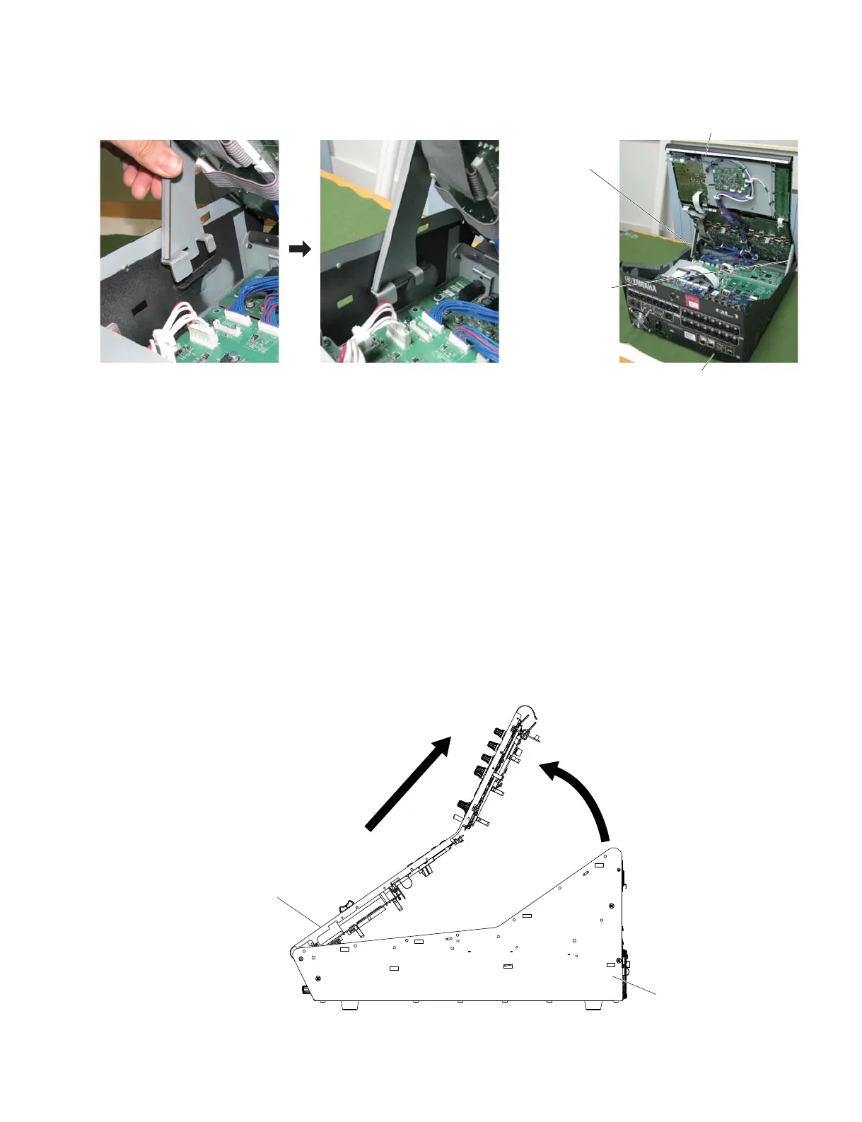
• Installing the Service Stay L, R(サービスステイ L,R の取り付け方)
2. Control Panel L Assembly
(Time required: About 7 minutes)
2-1
Remove the side pad assembly L and R. (See Procedure 1)
2-2 Remove the thirty (30) screws marked [130] and two
(2) screws marked [140]. (Fig. 2)
2-3 Lift the control panel L assembly from the rear side
and fi xit with the service stays L and R. (Photo 2)
* When you open the control panel L Assembly,
connector or connector assembly to prevent
damage, to be careful not too open the control
panel L Assembly.
2-4 Remove the control panel L assembly in the direction
of the arrow in Fig. 3.
BOTTOM L ASSEMBLY
(ボトムLAssy)
<Right side view(右側面)>
CONTROL PANEL L ASSEMBLY
(コンパネLAssy)
q
w
※ This photo and part name is QL1.
(この写真と部品名は QL1 です。)
2. コンパネ LAss'y
(所要時間:約 7 分)
2-1 サイドパッド Ass'yL,R を外します。(1 項参照)
2-2 [130] のネジ 30 本と [140] のネジ 2 本外します。
(図2)
2-3 コンパネ LAss'y をリア側から持ち上げ、サー
ビスステイ L,R で固定します。(写真 2)
※ コンパネ LAss'y を開く際は、束線やコネクタが破損
しないように、コンパネ LAss'y を開きすぎないよう
に注意してください。
2-4 コンパネ LAss'y を取り外す際は、図 3 で示す
矢印の方向へ外します。

 Loading...


